
A scene allowing the determination of a free return trajectory is provided with GE 2.3. A free return trajectory is a path that leaves orbit around a planet, loops around a moon of the planet and then returns to the vicinity of the planet. Free return trajectories were used during the Apollo program to ensure that if the engine failed to start at the point of lunar injection the spacecraft would return to Earth (some of the later missions departed from a free return trajectory to reach their landing sites).
The FreeReturn scene makes use of existing orbit transfer components and combines them into a visual representation of the trajectory:
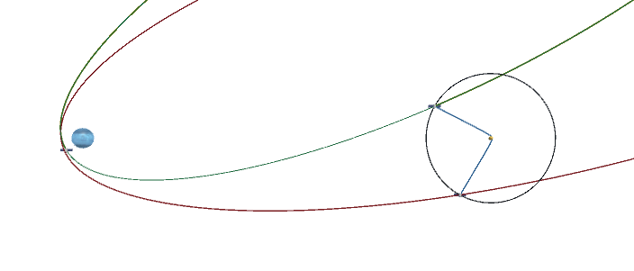
The green path shows the outbound path to the moon, blue the hyperbola around the moon and red the return ellipse to the planet. These paths are drawn in the co-moving frame, a frame in which the moon is fixed. In reality the moon will advance as the spacecraft travels towards it. The code in the FreeReturn scene takes this into account.
The completely general free return solution is a complex problem (one which GE will eventually provide a solution for). This implementation makes several simplifying assumptions:
- The orbit of the moon is circular
- The spacecraft is in a circular, equatorial orbit around the planet
- The transfer will occur in the equatorial plane.
The paths shown represent a patched conic approach to computing the transfer (ellipse-hyperbola-ellipse). This simplifies the calculation but when evolved with GE the actual path will differ for two reasons. First, the actual gravitational force will not exactly match the patched conic approximation. Secondly, as the ship swings by the moon on the hyperbola leg, numerical integration inaccuracies may result. This is minimized by the use of the Hermite integrator and disabling “Optimize Massless Bodies” in the GE inspector panel. Future GE work will help limit these issues by providing a patched conic “on-rails” evolution, and more fine grained numerical integration.
Using the Scene
The scene allows user control over the details of the transfer:
- the point of departure in the planet orbit is controlled by the A/D keys
- the point of arrival on the moon sphere of influence is controlled by K/L keys
- the transfer time is controlled with the S/W keys
- the X key starts the transfer and the spacecraft and moon will being moving
The scene has the usual camera controls (scrollwheel zoom) and number 1-6 control speed.
Implementation
The TransferCalcController component in the scene handles the orbit transfer calculations in the ComputerTransfer() method with some additional code in the Update() method. The approach used is:
- Given the departure and arrival points plus the desired transfer time, use the LambertUniversal class to find the velocity required to leave the planet. (This script also finds the velocity at the arrival point. It is retrieved with GetFinalVelocity()
- Adjust the final velocity to the moon’s frame of reference and determine a hyperbolic orbit around the moon. This is accomplished by having a “phantom ship” positioned at the SOI arrival point and using an OrbitSegment component.
- The return ellipse is determined by computing the position and velocity at the SOI exit point (using a methods added to OrbitHyper for this purpose: MirrorPhysPosition() and MirrorPhysVelocity(). ) This is then assigned to another “phantom ship” with an OrbitPredictor.
When the X key is pressed, the initial velocity computed in step 1 above and the departure position are adjusted. This is required to account for the fact that the moon will be moving as the ship transits to the SOI. The corrected values are then applied to the spaceship and evolution begins. The phantom ships are removed.