
Overview
Gravity Engine (GE) provides a powerful, accurate physics engine to simulate gravity including:
- Double-precision N-body simulation and “on-rails” patched conics on a per-body basis
- Creation of orbits with control of shape, inclination and orientation.
- Simple components for manual maneuvers and any-orbit to any-orbit transfer or rendezvous
- Rocket engines to simulate launch from a planets surface modeling fuel consumption (rocket equation)
- Earth Atmosphere model
- N-body trajectory prediction
- Solar system model for ANY planet, comet or asteroid
- Gravitational collisions with particle ejection effects
- Centralized control of simulation units (km, AU, arbitrary), overall evolution speed, distance and mass scales
It is not necessary to understand the details of the gravitational physics. Gravity can be added to a scene without scripting.
Code Documentation: http://nbodyphysics.com/gravityengine/html/
Support: nbodyphysics@gmail.com
Suggested on-boarding sequence:
New in 11.1 (March 2023)
OrbitPredictor now supports a “de-jitter” feature to avoid jumps in orbit elements for near-circular and/or near-equitorial orbits.
Add a callback for SGP4 satellite decay and better logging of satellite decay.
Export of a satellite state as a SGP4 compatible two-line element set (TLE).
Bug Fixes:
Fix OrbitPoint update bug plus several issues in demo scene controllers. See README at top level for more details.
Code Documentation: http://nbodyphysics.com/gravityengine/html/
Contents
Package Overview
Scenes
Getting Started
| Folder | Scene Name | Description |
|---|---|---|
| GettingStartedv3 | A simple "hello world" scene in which a ship is placed under the influence of a planet with a simple engine fire command. | |
| Orbits-Tutorial | Demonstration of OrbitUniversal, the component used to place objects in orbits around other bodies (off-rails or on-rails) | |
| InOrbit-Manual | ManualShipControl | Demonstrates click and drag ship manuevers at current ship location. |
| InOrbit-Manual | ManualShipControlWithOrbitPoint | Demonstrates click and drag maneuvers at a future point on a ships path. |
| InOrbit-Manual | ManualShipControlOrbital | Same as ManualShipControl but in ORBITAL GE units. |
| InOrbit-Transfers | TransferShip | Shows the use of TransferShip to change orbits at the current ship position. |
| InOrbit-Transfers | TransferShipWithOrbitPoint | Shows TransferShip operating at a future point in a ships orbit. |
Tutorial Scenes
Tutorials are also available from the Title bar in a drop down and the NBodyPhysics YouTube channel: https://www.youtube.com/channel/UCxH9ldb8ULCO_B7_hZwIPvw
| Scene | Description |
|---|---|
| Getting Started | Add a spaceship in an orbit with a simple thrust control. |
| Orbits Tutorial | Demonstrate the use of OrbitUniversal and N-body vs on-rails evolution. Illustrates the use of the OrbitPredictor component to show an orbit in the scene. |
| Show the use of the OrbitPoint component. | |
| Spaceship manual maneuvers | |
| Spaceship Orbit Transfers | |
| Overview | Central star with an orbiting planet and particle ring. |
| T1 - Binary Stars | Create a binary pair of stars that orbit their center of mass. |
| T3 Collisions | Demonstrate the ways collisions can be handled in Gravity Engine. |
| T4 Particles | Setup particle systems (box, orbiting ring) |
| T6 Trajectory Prediction | Full N-body look-ahead modelling of trajectories with time markers. |
Demonstration Scenes
The scenes in Scenes/Demos are provided to illustrate a specific aspect of GE.
| Folder | Scene | Description |
|---|---|---|
| 3BTrajectory | Three body solutions with a spaceship and trajectory prediction. | |
| AddDeleteTest | Interactive add/delete of massive, massless and Kepler orbiting bodies. | |
| EarthWithJ2_SunSynch | Uses J2Force to evolve satellites in an oblate gravitational field. Includes an SGP4 satellite for comparison. | |
| ForceCustom | Demonstrates a custom (non-gravity) central force and its effect on planets and particles. | |
| Force Inverse R | Shows a 1/R (vs gravity's 1/R^2) force. | |
| FrameRateTest | Automatically add massive bodies until the frame rate drops to 58 FPS. Reports N. | |
| LagrangePoints | Use the LagrangePoint component to position ships at all 5 Lagrange points. | |
| OrbitDecay | Shows how a simple add on script can create decaying orbits. | |
| OrbitPoint | OrbitPoint places a marker or nbody at a specific location on an orbit (apoapsis, ascending node etc.) | |
| RandomPlanets | Auto-create planets, binaries and moon at run-time. | |
| Reposition | Re-locate and rotate/zoom the entire universe. | |
| ShipOnOffRails | Example of a controller that moves a ship off rails when firing an engine then back on rails. | |
| ThreeBodies | Shows the three body configuration generator. | |
| TimeOfFlight | Compute the time of flight to a point on an orbit. | |
| SGP4_Celestrak | SatelliteFromCelestrak | Demonstrates several satellites (e.g. ISS) with orbits loaded from two line elements. Also shows how to load from a file of TLEs. |
| SGP4_Celestrak | SGP4Propagation | Demonstrates SGP4 evolution in Earth orbit. |
| SGP4_Celestrak | SGP4PropagationScaled | As above but scaled. |
| SolarSystem | SolarSystemOuter | Model of outer solar system. |
| SolarSystem | SolarSystemInner | Model of inner solar system |
| SolarSystem | SolarSystemFull | Model of full solar system |
| SolarSystem | SolarSystemInner-SetTime | Model of inner solar system that allows date and time to be set. |
| SolarSystem | SolarSystemLaunchWindow | Determine launch window for Hohmann transfer to a selected planet. |
| TPI-RelativeMotion | LunarTPI | Models final lunar rendezvous phase of Apollo 11 using trigger angle targeting. |
| TPI-RelativeMotion | RelativeMotion | Illustrates relative motion computation and display of rendezvous. |
| Transfers-Hohmann | Circularize | Use TransferShip to circularize a ship orbit. |
| Transfers-Hohmann | HohmannGeneral | Use transfer ship to demonstrate a general Hohmann transfer. |
| Transfers-Hohmann | HohmannRails | Demonstrate an on-rails Hohmann transfer with time rewind using TransferShip. |
| Transfers-Hohmann | HohmannXfer | Generic Hohmann transfer using TransferShip. |
| Transfers-Lambert | LambertRendezvous | Shows TransferShip used to establish a Lambert rendezvous. |
| Transfers-Lambert | LambertToPoint | TransferShip example of Lambert transfer to a specified point. |
| Transfers-Lambert | LambertXferDL | Demonstrates a controller that selects a target orbit and a phase in the target orbit for Lambert transfer. Dimensionless units. |
| Transfers-Lambert | LambertXferDL-OnRails | As above, but "on-rails" |
| Transfers-Lambert | LambertXferSolar | As per LambertXferDL but in SOLAR GE units. |
Mini-Games
Gravity Engine provides a number of mini-games. These scenes have more substantial controller classes and game logic to provide examples of how Gravity Engine elements are used to accomplish game implementation objectives.
| Scene | Description |
|---|---|
| MoonXfer/EarthMoonXfer | This game provides a UI that allows orbit transfers and rendesvous as well as manual control of manuevers in a Kerbla-style drag of orbit handles. |
| MoonXfer/PlanetMoonXfer | The same as EarthMoonTransfer but in dimensionless units. |
| FreeReturn/FreeReturn | This scene allows a free return trajectory to be determined. The path is show in the co-rotating frame. The FreeReturnController class handles all the computation. Free Return Page |
| FreeReturn/FreeReturnMoon | Same as FreeReturn but in Orbital units and using values for the Earth and Moon. Free Return Page |
| FreeReturn/FreeReturnOnRails | FreeReturn with all objects on rails allowing a time slider to be used. The same controller code (FreeReturnController) is used. |
| MoonToEarth | Planning for a burn to escape the moon and return Earth |
| LaunchOrbit2 | Launch from the surface of the Earth into orbit using the RocketEngine components. Supports a pitch vs time component or user-input to control the ascent trajectory. |
| Re-entry | Shows the use of the EarthAtmosphere model to slow a ship in orbit and models the re-entry path. |
| Docking | Example of how to combine GE and rigidbody physics in a docking simulation. |
Fundamental Classes
There are three key classes involved in adding gravitational evolution of objects to your Unity project:
- GravityEngine – the script that performs all the physics calculations and updates object positions in the scene.
- NBody – a script attached to all bodies to be controlled by the GravityEngine. Used to specify their mass and initial velocity.
- OrbitUniversal – added to an NBody to place it in a specific orbit and evolve freely (GRAVITY_ENGINE mode) or to move “on-rails” (KEPLER mode).
The GravityEngine class is the central controller for all the gravitational physics in the scene. All objects that require gravitational motion are explicitly added or detected by the GE at startup. The GravityEngine then performs the physics calculations on each FixedUpdate and updates the transforms of all objects under its control.
GravityEngine is a very flexible gravitational physics engine that provides:
- Choice of dimensionless or real-world units for distance, mass and time
- Ability to scale chosen units to achieve the desired game “feel”
- Advance options to select:
- Physics algorithm
- Time steps per frame for algorithms
- Performance optimizations for gravitational particles
- Options to allow objects to be detected automatically or added via scripts
NBody Orbit Scripts
Finding the exact initial velocity that creates a specific orbit can be challenging, requiring either physics calculations or trial and error. To eliminate the need for this there are a number of scripts that can be used in addition to the NBody script to control the initial conditions of a body to create a specific orbit.
These scripts will show the path of the orbit in the scene view as the objects are added.
There are several options for adding initial conditions or constraining the motion of an NBody object:
- OrbitUniversal – start a body in a specified orbit around another body. The body can be moved using gravitational force, or it can move in a fixed path using Kepler’s Equation. Elliptical orbits have eccentricity < 1, parabolic have eccentricity = 1 and hyperbola eccentricity > 1.
- Binary Pair – initialize a pair of NBody objects so that they form a binary pair with specified orbits. Based on interactions with other bodies the actual orbit followed may change.
- FixedObject – object does not move, however it’s mass will influence other objects in the scene
- OrbitPoint – place a game object or NBody at a specific point in an orbit (e.g. apoapsis, periapsis, ascending node…)
- LagrangePoint – set the initial position at a specified Lagrange point (with an optional offset in position and velocity)
NBody Course Changes
An NBody object under GE control will move according to the N-body forces from all the massive objects in the scene (unless it has been placed “on-rails” in a specific orbit around a mass). Course changes and maneuvers can be accomplished in a number of ways:
- Direct velocity changes using ge.AddImpulse()
- Creating a Maneuver object that defines a velocity change at a specific time and applies that. This maneuver is then added with ge.AddManeuver()
- Using TransferShip or one of the Orbit Transfer classes to generate and add the maneuvers required for a specific type of transfer.
Changes that require an impulse at a specific physical condition (e.g. when ship reaches a specific distance from a moon) can be accomplished with a GETrigger.
Gravitational Particles
GravityEngine allows particle systems to move based on the gravitational field. Particles are treated as massless bodies and are subject to the gravity of NBody objects in the scene. An existing particle system can be placed under the control of the GravityEngine by adding a GravityParticles script.
The GravityParticles script can also have an optional delegate that controls the initialization of the particles. Several delegates are provided:
- DustBall – a spherical shell of particles moving at a specified initial velocity
- DustBox – a 3D rectangle of dust with individual control over size in (X,Y,Z)
- DustOrbit– a ring of particles that orbit around a massive NBody parent. The orbit parameters can be controlled. Useful for effects like planetary rings.
Collisions
Collisions between NBody objects are detected using Unity colliders. Since these collisions are due to gravitational interactions, the NBodyCollision class handles updates to the physics. The collision can be handled in one of three ways:
- Absorb
- Bounce
- Explode
- Explode or Bounce (based on contact velocity)
In each case the physics engine is updated as required and momentum and energy are conserved.
Documentation
Gravitational Objects
GravityEngine
GravityEngine is the primary class in the asset. For gravitational motion the scene must contain an object with a GravityEngine component. This can be added via the Unity Menus (GameObject/3D Object) or by adding the GravityEngine script to an existing object in a scene.
GravityEngine evolves objects that have an NBody script attached. NBody defines the mass and initial velocity. The GravityEngine can automatically detect all NBody objects in a scene when it starts (the default), be given an explicit list of objects, or objects can be added by script calls to GravityEngine.AddBody().
The engine operates on the FixedUpdate() cycle to ensure that physics evolution tracks game time. In some cases the exact amount of evolution in a specific cycle will vary slightly depending on whether the evolution algorithm has run ahead or behind on previous cycles.
In general the GravityEngine attributes cannot be changed while the scene is running (with the exception of the timescale attribute).
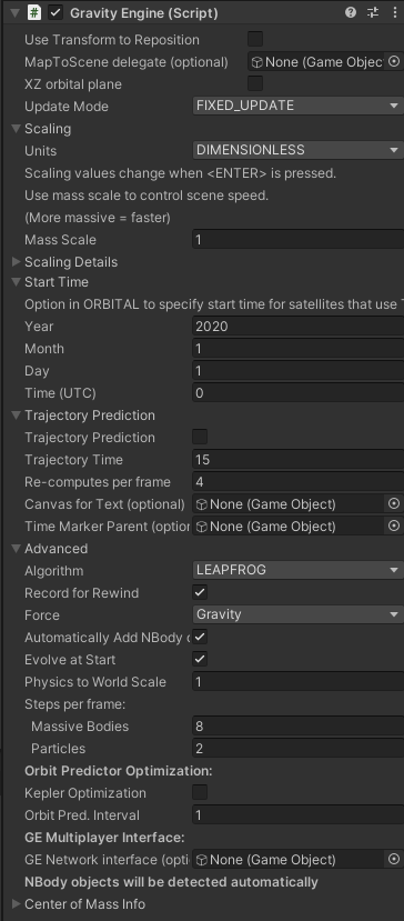
The inspector view shows the parameters. There are a large number of options here, since this is the central class in the asset. The defaults will suffice in many cases.
Use Transform To Reposition: If enabled the transform of the GravityEngine game object is used to set the origin, rotation and scale of the physics objects in the scene. NOTE: These are all still initially defined with respect to the (0,0,0) origin of the scene and are re-positioned at run time. The re-positioning is dynamic and can be adjusted at run-time. For an example of this see the Demos/Reposition sample scene.
Map To Scene Delegate (optional): This requires a game object that implements the GEMapToSceneInterface. If present this interface will be called every Update cycle to do the mapping from gravity engine internal physics units to the scene position. Linear scaling can be done via the “Use Transform to Reposition” checkbox.
XZ Orbital Plane: The classes that create orbits (OrbitUniversal, BinaryPair etc.) by default create these orbits in the XY plane (when inclination is zero). This corresponds to the way in which orbits are defined in the physics literature. This makes the Z co-ordinate the out-of -plane or “up” direction, which does not correspond to the usual convention in the Unity editor. It does, however, allow a 1-1 correspondence with examples in the physics literature and this is useful when using data from external sites.
When enabled, this flag changes the default behavior to create orbits in the XZ plane. This has an additional benefit in that the difference between Unity’s left-handed co-ordinate system and the right handed physics co-ordinates is compensated for and the appearance of ascending and descending nodes matches those in the physics diagrams. See Orbital Elements and Unity’s Left-Handed Co-ordinate System
Update Mode: The main physics loop in GE runs on the fixed intervals of fixed update (as does Unity’s own internal rigid body physics). This will in general result in a difference in the game code update rate and the fixed update rate. By default GE updates the transforms for NBody objects on the fixed update cycles. In some cases this can result in visual jitter at some choices of scale. GE provides control over this mechanism to solve the jitter problem by allowing a choice of update mode:
- FIXED_UPDATE: (default) run physics loop and transform updates on FixedUpdate()
- FIXED_INTERPOLATE: run physics loop on fixed update but update transform position updates on the Update cycle and use interpolation to adjust for the difference in times
- UPDATE: run physics loop on the update cycle and update transforms during this Update
SCALING
Units: Gravity Engine allows a choice of units in the game positions. In gravity force calculations it is convenient/efficient to set the force constant G=1.
The follow unit choices are supported:
- DIMENSIONLESS: Arbitrary units used directly in the force calculations. When selected the inpector allows Mass Scale and Time Scale to be varied.
- SI: Units are in m/kg/sec. See Real-Unit scaling below.
- ORBITAL: Units are km/1E24 kg/hours. See Real-Unit scaling below.
- SOLAR: Units are AU/1E24 kg/years. See Real-Unit scaling below.
Mass Scale: The GravityEngine allows for the changing of mass scale of all NBody objects in the scene with a single parameter. Initial velocities of NBody objects will also be scaled such that paths taken by the bodies will not change when mass scale is altered.
Adjusting mass scale can be a useful way to change the speed at which things happen in the scene. As the mass scale increases, forces between the bodies increase and the evolution in the scene happens faster. This is the most common technique for adjusting the overall speed of the evolution in the scene.
Mass scale adjustments do not affect the amount of CPU time used in gravitational evolution.
To delve further, see the section Scaling below.
TimeScale: The timescale controls the ratio of time in “the physics world” as compared to time in the game. It can be used to control the overall speed but this happens in a way that affects the CPU time used for gravitational evolution. A timescale value larger than 1 performs more calculations per cycle. A timescale value of less than one will result in fewer calculations per cycle. In either case the evolution calculations will have the same accuracy.
Real-Unit Scaling: When using non-DIMENSIONLESS units the inspector allows a choice of Unity units per distance unit (e.g. Unity units per km). Changing this scale will automatically adjust the distances between all objects in the scene.
Time scale is also adjustable for non-DIMENSIONLESS units (e.g. game sec. per hour). This change, combined with the length scale and use of G=1 in the force equation results in the internal calculation of a mass scale that ensures the correct evolution in the scene.
START TIME
Start can be used when the units are ORBITAL. When OrbitUniversal initialization information is performed using two line elements from Celestrak, the start time is used to determine the initial position for these bodies. The start time specified must be later than the time in the two-line element information for the satellite.
TRAJECTORY PREDICTION
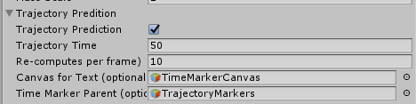
Trajectory prediction control in the Gravity Engine component works in tandem with Trajectory components added to NBody objects in the scene. Instructions for the configuration of these is provided in more detail below and in Tutorial 6: Trajectories.
Trajectory Prediction (Checkbox): If enabled, the GE will simulate the future progress of all massive and massless bodies in the scene for the time indicated by “Trajectory Time”. NBody objects that have a child with a Trajectory component will have the future path rendered via their Line Renderer components.
If there is a call to ApplyImpulse or ResetTrajectory then the future evolution will be re-computed.
Trajectory Time: The time into the future that all objects will be evolved for to determine trajectories for those objects with Trajectory components.
Frames Between Resets: The number of frames that must elapse before a new ResetTrajectory (directly or via ApplyImpulse) can be performed. Since a trajectory re-computation requires the scene be evolved for the time indicated by “Trajectory Time” this can be a CPU intensive activity. Imposing a non-zero limit ensures that this does not occur too often.
Canvas for Text: The Trajectory component can optionally add labels to indicate the future time along the trajectory. These text components require a World View Canvas in the scene. This field provides the reference to the Canvas for use by the Trajectory components.
ADVANCED
Algorithm:There are a number of possible algorithms for gravitational evolution. They vary in accuracy and computational complexity.
- Leapfrog: The best default choice. This is a computationally cheap algorithm with a fixed time step that conserves energy well.
- Hermite: A variable time-step algorithm that will spend more CPU cycles when objects get close to improve accuracy.
- AZTTriple: A special case algorithm for ONLY three bodies. It is a “regularizing integrator” that allows objects to get infinitely close without numerical instability. Typically used in conjunction with the ThreeBodySolution class.
Record For Rewind: Enable the recording of velocity changes, impulses, maneuvers and add/deletes in the rewind manager to enable time to be reversed and changes in body motions to be undone. Detailed information.
Force: The force chooser allows control over the force law used in the engine. The default choice is standard gravity (Newton’s force law). Other choices are described in the force modification section.
Automatically Add Nbodies: When selected the GravityEngine will examine all objects in the scene (during the Awake phase) and take control of the evolution of those bodies that have an NBody or GravityParticles component.
In cases where this behavior is not desired (e.g. a player spaceship is not moved while the rest of a solar system is) this option can be unselected. In this case the inspector will show a new section to list the bodies that should initially controlled. Existing scene objects with an NBody component can be dragged onto the Bodies list.
In both cases additional bodies can be added via calling GravityEngine.AddBody() and particles systems via GravityEngine.RegisterParticles()
Evolve At Start: By default the GravityEngine will begin evolving all the NBody/GravityParticles objects in the scene when the system starts. Clearing this checkbox can disable this. When cleared, evolution will start when GravityEngine.SetEvolve (true) is called.
Physics to World Scale: A scale factor used to adjust the distance scale used in the physics engine to the Unity positions in the scene. Physics positions are determined by dividing their Unity positions by this factor.
For example, if two bodies are 10 units apart and the physics to world scale is 1 the GravityEngine will use 10 as the distance between bodies. In some initial conditions from the scientific literature the distance scale defined in may be in a very small range, typically (-1..1). It is easier to use these values in the physics calculations because it avoids the need to scale masses and velocities. In this case, setting the physics to world scale to 10 and then positioning the bodies 10 units apart will result in them being scaled down by 10 in the physics calculations and the physics algorithm will see them as 1 unit apart.
This parameter is used by the the ThreeBodySolution code to allow three body physics that is specified in the range of [-1,1] to be displayed using a larger scale in a Unity scene.
Steps Per Frame (Massive Bodies): This parameter defines the approximate number of times per frame the physics engine will re-calculate positions for NBody objects. A larger number will result in more accurate physics at the cost of more CPU effort. Default value is 8.
Steps Per Frame (Particles): This parameter defines the approximate number of times per frame the physics engine will re-calculate positions for particles. A larger number will result in more accurate physics at the cost of more CPU effort. Default value is 2.
Orbit Predictor Optimization
Orbit predictors by default will re-compute the orbit elements for an NBody each fixed update and then generate the points required to display that orbit in the scene. This can become a significant workload in cases with large numbers of NBodies and can be a performance limiter. Several options exist to optimize the performance of orbit predictors.
Kepler Optimization: Objects in a KEPLER_MODE (“on-rails”) orbit do not change their orbital elements unless there is some change to the NBody via e.g. ApplyImpulse() or or a direct call to the orbit to change the position and/or velocity. When selected this flag indicates that OrbitPredictors can skip updates if the orbit elements AND the center object of the orbit have not changed.
This produces very significant performance gains when there is a fixed center object and numerous objects in Kepler mode orbits around it.
Orbit Predictor Interval: This setting defines the interval (in frames) between orbit predictor updates. By default they are updated every frame (interval=1). To improve orbit predictor performance set to a higher number. This field cannot be adjusted at run-time.
GE Multiplayer Interface (optional)
If a game object implementing the GEMultiplayer interface is provided then all add/remove and changes to NBody objects in gravity engine will result in callbacks to this interface.
Center of Mass Info
The center of mass of all the objects in scene is shown here when the scene runs.
Set Center of Mass: If set, this option ensures the center of mass of a system stays at the specified position and velocity. This field may be useful in a case where a heavy planet is placed in orbit around a star. GE will provide the planet with a velocity and this will result a small net velocity of the combined system, since the star is not given a corresponding velocity unless this option is selected. Left unchecked the system would have a net drift velocity in the scene.
An alternative is to attached a FixedBody component to the star to ensure it does not move, or to use a BinaryOrbit component.
Nbody
The GravityEngine evolves objects with an NBody script attached to them.
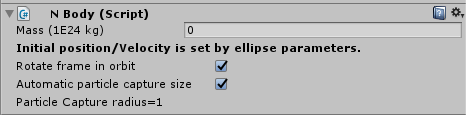
The inspector view for a general NBody object depends on the choice of units. For DIMENSIONLESS units it is:
For a scene with real-world units it is:
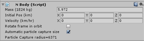
Mass: Mass is specified in dimensionless units. A value of less than zero will be set to zero.
Initial Pos: In those cases the object position is set by the transform component in the usual manner. When real-world units are used the position in real-world units is specified here and the objects position in the scene is calculated based on the length scale specified in the GravityEngine component.
This field is not used in dimensionless units.
Velocity: A Vector3D specifying the initial velocity of the Nbody. If the initial conditions are controlled by an additional component (e.g OrbitEllipse) this field may not appear. The inspector view for an object that has another component providing initial conditions for motions (i.e. an OrbitEllipse or BinaryPair component) will look like:
In this case the initial velocity is determined by another component.
Automatic Particle Capture Size/Particle Capture Radius: If automatic capture size is selected, the particle capture size will be taken from the scale of a child object containing a MeshFilter object. This corresponds to typical use of NBody objects in which a child is a 3D Sphere. This ensures the particle capture size matches the sphere.
Any particle that enters the capture radius of an NBody will be inactivated.
If the automatic checkbox is cleared, a value for capture radius is required.
Orbits
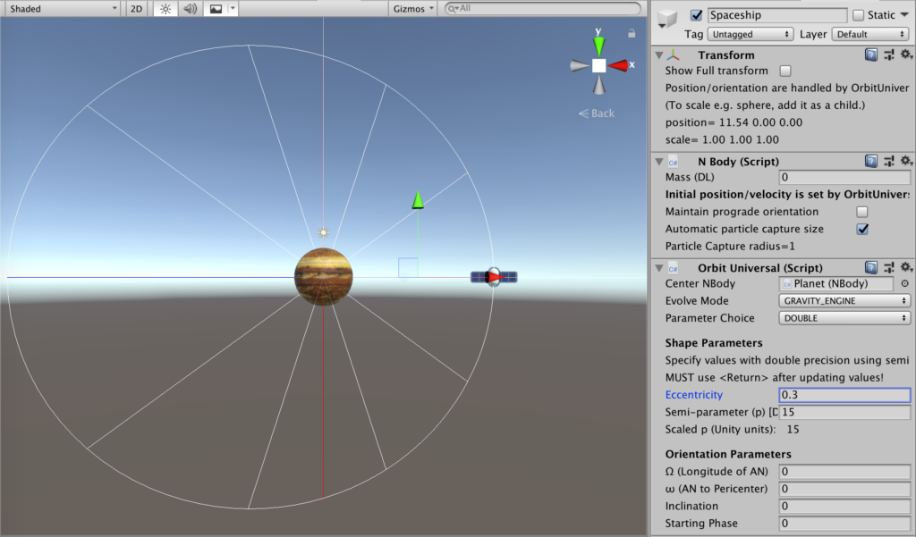
OrbitUniversal
OrbitUniversal is the best choice for specifying the orbit of an object in GravityEngine. It replaces the OrbitEllipse and OrbitHyper in versions before 3.0 (these classes are still supported).
OrbitUniversal provides:
- double-precision orbit parameters
- a selection of input methods in the inspector (major axis, apogee/perigee, semi-parameter)
- NBody (GRAVITY_ENGINE) mode or on-rails (KEPLER_MODE)
- support for ellipse (e < 1), parabola (e = 1) or hyperbola (e > 1) orbits
- on-rails mode supports ApplyImpulse() to allow on-rails spaceships to change their orbits
The OrbitUniversal by default assumes that the attached NBody object will be subject to the gravitational influence of all the objects in the scene. This corresponds to GRAVITY_ENGINE mode. In this case the OrbitUniversal computes the required initial position and velocity for the orbit and then leaves the evolution up to the gravity engine. This means that if the object in orbit is perturbed by some body other than the one it is orbiting, the orbit will change due to the perturbation. In some cases a game scene may wish to avoid the stability issues caused by these perturbations and keep the initially specified orbit. This is done by selecting KEPLER_MODE. In this case the object moves in the specified orbit according to Kepler’s law and is not affected by perturbations from other objects. This operation is also referred to as “on-rails”. Changes in a Kepler mode orbits are still permitted via orbit transfers or ApplyImpulse. These alter the OrbitUniversal to a new set of orbit parameters based on the transfer/impulse provided. If a scene requires time reversal or requires a series of independent OrbitUniversal segments (e.g. a patched conic path) then OrbitUniversal can be used in conjunction with KeplerSequence as described in the section below.
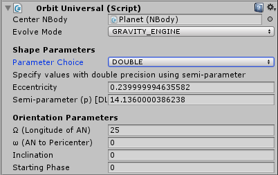
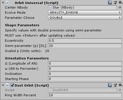
Center NBody: Displays the name of the object around which this body will orbit. This is detected automatically if the object is the child of another NBody object. It can also be set explicitly to any object in the scene with an NBody component.
Evolve Mode: There are three modes in which OrbitUniversal operates:
GRAVITY_ENGINE mode will initialize the velocity of the NBody to launch it on the specified orbit. Forces from other bodies may affect the NBody and affect its path. Changes made to the body via GravityEngine.ApplyImpule() will change the path the object takes. This is the mode that is used when correct physics is important.
KEPLERS_EQN mode will force the planet to follow the specified orbital path. The mass of the NBody will affect other bodies but they will not affect it. This mode is used when deterministic motion is required (at the cost of physical accuracy). It can also be useful in large orbital systems – since Kepler’s equation uses less CPU than calculating all the forces between bodies in a large orbital system.
SGP4_PROPAGATOR mode can be used if the GE units are ORBITAL. This evolves a satellite in Earth orbit using a simplified general perturbation model developed to model effects of atmosphere, non-spherical gravity and (for larger orbits) lunar gravity effects.
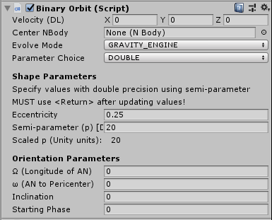
Shape Parameters
Parameter Choice: A chooser to select how the shape is to be defined.
| Parameter Choice | Description |
|---|---|
| DOUBLE | Use eccentricity (e) and semi-parameter (p) |
| DOUBLE_ELLIPSE | Use eccentricity and semi-major axis (a) |
| ELLIPSE_MAJOR_AXIS_A | Use eccentricity (e) and semi-major axis (a). Semi-major axis is only defined for an elliptical orbit. e < 1 is enforced. |
| ELLIPSE_APOGEE_PEROGEE | Use the perigee (closest approach) and apogee (farthest distance) to define an elliptical orbit. |
| ECC_PERIGEE | Use eccentricity (e) and perigee (closest approach) to specify an elliptical or hyperbolic orbit. |
Orientation Parameters
The orientation parameter section specifies:
- Ω (longitude of the ascending node)
- ω (angle from ascending node to pericenter)
- Angle of inclination
For details see the illustration on the Wikipedia: Orbit Elements. Viewing the orbit in scene view and tinkering with value will help develop some intuition about these parameters.
Starting Phase: This value defines the starting position of the object in the orbit.
“On-Rails” Options: KEPLER and SGP4
The OrbitUniversal component can “take control” of the evolution of an NBody and evolve it algorithmically to give a deterministic path that is not subject to the stability and chaos concerns that come with general N-body gravitation. For example, if you wish to build a small system of star, planets and moons and do not want to worry about the stability of the system, you can place all the planets and moons in Kepler mode and they will evolve in their defined ellipses without perturbing each other and causing chaotic orbits.
Similarly, spacecraft can be assigned to KEPLER orbits and they will evolve according to Kepler’s law around their designated center object. The objects can still make orbit changes via ApplyImpulse() or maneuvers and new KEPLER orbits with the updated orbital parameters will be determined.
KEPLER orbital evolution is idealized to the “textbook” motion around a central body. A more sophisticated model is available for satellites in Earth orbit, the Simplified General Perturbation Model v4 (SGP4). This model for satellite evolution includes effects of atmosphere, non-spherical Earth, and the influence of the moon. Objects in such orbits can also apply impulses and maneuvers and the orbit will adjust. Note that objects in SGP4 orbits can also decay. OrbitUniversal provides a callback that can be attached for this scenario: AddSGP4DecayCallback. it is recommended that this callback remove the NBody from GE evolution.
KeplerSequence
The KeplerSequence component is added to an NBody that has an OrbitUniversal in cases where the scene wants to make use of time-reversal or in a case where a script wishes to compute a series of OrbitUniversal segements to implement a patched conic segment.
An example of time reversal use can be found in the Demos/Scenes/Transfers-Hohmann/HohmannRails scene. After the transfer has been computed the KeplerSequence inspector shows the segments that result
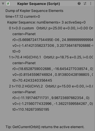
Note that each segment has a start time. This allows the correct segment to be chosen as the GE time value is changed. Note that for a scene to be time reversible every element in the scene needs to be time reversible.
GE automatically manages KeplerSequence objects and as commands to change their path occur via ApplyImpulse() or maneuvers new OrbitUniversal segments will be added.
There are also example scenes that use KeplerSequences to provide a series of patched conics for transfer to/from the moon. These can be found in the MiniGame folders FreeReturn and OnrailsMoonToEarth.
OrbitPredictor
The OrbitPredictor script predicts the orbital path a body will take given the current velocity of the body and draws the path using a LineRenderer. The projected orbital path updates on each FixedUpdate() cycle – so the influence of user provided velocity changes or changes due to interactions with masses other than the central body will be reflected in the updated path.
Orbit prediction is done using a two-body calculation, transforming the position and velocity with respect to the center body into orbital parameters. The predicted orbit will be accurate if the center body is the dominant source of gravity. If there are other significant sources of gravity in the scene the prediction will not be accurate. [Solving the general orbit prediction problem is not mathematically possible in most cases and would require a simulation of the future evolution of the system – trajectory prediction an be used in this case. See below].
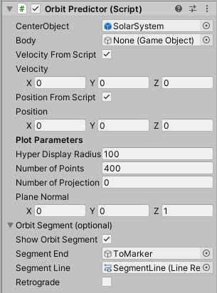
CenterBody: The NBody containing object around which the orbit should be calculated.
Body: The body for which the orbit will be calculated. The orbit will be predicted based on the current value of the position and velocity for the body in GE. If both position and velocity from script are selected then an Nbody reference is not required, the orbit resulting from the position and velocity determine the orbit.
Velocity From Script: Unselected the component will automatically retrieve the velocity of the body from GE. This will result an orbit segment that shows the future path of the object. When checked a scene controller can modify the velocity to show a “what if” scenario and display the orbit that results with the specified velocity. The velocity can be set by a call to SetVelocity(). The initial velocity is given by the Velocity value from the inspector.
Position From Script: When unselected the component will retrieve the position from GE. If selected the position is taken from the value in the inspector. It can be changed at runtime with SetPosition().
Dejitter Orbit Elements: When selected, some debouncing is applied when the orbit is near circular or near equitorial to avoid jumps in the argument of perigee or RAAN. For example when an orbit is non-circular then the notion of periapsis is well defined as the point of closest approach and the phase is measeured from this point. If the orbit becomes circular, then there is no closest point and the argument of perigee is defined to be 0 and the phase is measured from there. This can cause a discontinuity in the reported phase. Selecting dejitter does not entirely resolve this (it is fundamental to the orbit parameters) but it does add some hysteresis so orbits near the circular/flat threshold do not “dither” between e.g. circular and elliptical.
Plot Parameters:
Hyper Display Radius: When the predicted orbit is a hyperbola it will extend to infinity. This parameter controls the maximum distance from the enter that the hyperbola will be displayed.
Number of Points: The number of points to use in the line renderer to represent the orbit.
Number of Projection Points: (optional, default 0) When the orbit is inclined visibility of this fact can be enhanced by drawing lines from the orbit to a reference plane (defined by the plane normal parameter). When non-zero this setting will enable the drawing of such lines.
Plane Normal: Reference plane to show inclination of on orbit with respect to. Only relevant if Number of Projection points is non-zero.
Orbit Segment (optional):
Show Orbit Segment: When enabled a second line renderer will be used to draw a segment of the orbit from the current position to the Segement End game object.
Segment End: A game objects on the orbit indicating the end of the segment to be displayed.
Segment Line: A line renderer to represent the orbit segment.
Retrograde: If enabled draws the segment in the retrograde direction.
Adding an OrbitPredictor component will automatically add a LineRenderer component. To see the orbit, the Line Renderer component must be correctly configured (i.e. add a suitable material)
The orbit predictor script adds an OrbitUniversal component to the object on which it resides. It instantiates a helper class OrbitData that determines the orbit parameters based on the velocity of the object and the center object.
OrbitSegment
The OrbitSegment component shows a section of an orbit from an NBody to a specific point. This can be useful when showing the path that will result from an orbit transfer. It is used for this purpose in the Lambert demo scenes. The velocity used for the prediction can be taken directly from the NBody (to show the current path) or may be set by a script based on a maneuver calculation (as is done by e.g. LambertToPointController).
The inspector view of this components is:
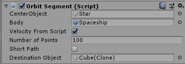
The num points, center body and velocity from script are the same as an OrbitPredictor and are described above.
Short Path: Given two points on an ellipse the segment displayed could be the shortest distance along the ellipse or the longer path. This toggle determines which is displayed.
Destination (optional): A game object in the scene that specifies the point on the ellipse that is the end of the segment. If the point is not on the ellipse, the code will take the point on the ellipse in the direction of the destination. If left empty the destination can set by the SetDestination() API call using the internal GE position for the destination point.
OrbitRenderer
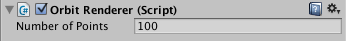
The OrbitRenderer component works in conjunction with a LineRenderer to show the inital orbit path in the scene view during game play. The script must be attached to an object with an OrbitUniversal (or legacy OrbitEllipse/OrbitHyper) component – from which the orbit path will be determined at the time the scene starts.
A body may not exactly follow this path if there are interactions with other masses. The OrbitRenderer is attached to a game object that is a child of the NBody to allow for separate material selection.
To see the orbit, the Line Renderer component must be correctly configured (i.e. add a suitable material)
A prefab “OrbitPath” is provided.
OrbitPoint
The OrbitPoint component can be used to position a game object or NBody at a specified point in an orbit determined by an OrbitPredictor. Example uses include showing the location of apoapsis/periapsis or a location for a future manual maneuver. The parameter required depends on the type of point chosen in the OrbitPoint:
| Type | Description | Parameters |
|---|---|---|
| Apoapsis | Furthest point from the center body (ellipse only) | none |
| Periapsis | Point of closest approach to the center body. | none |
| Altitude_1st | Point on the orbit at the specified altitude (first point starting counter-clockwise from periapsis) | Altitude |
| Altitude_2nd | Point on the orbit at specified altitude (second point) | Altitude |
| Ascending Node | Point where an inclined orbit passes through XY plane in ascending direction [1] | none |
| Descending Node | Point where an inclined orbit passes through the XY plane descending [1] | none |
| Fixed Time | Point on the orbit a fixed time ahead of a specified body in the orbit. | TimeRefBody: Body with reference to which time is given Time: time ahead of body |
| Phase | Phase in the orbit | phase |
| Phase from Mouse | Use mouse to click and designate the phase of the orbit | Scene Camera: Used to map clicks into GE positions |
[1] Due to the co-ordinate system used in Unity compared to the convention in astrodynamics the ascending and descending nodes will appear switched for orbits in XY mode. See the discussion and the video.
When attached to a game object, the script will position the game object at the correct point on the orbit. When attached to a game object that also has an NBody, the script will update the NBody position in GE based on the OrbitPoint parameters.
OrbitPropagator
OrbitPropagator is a class that can be used within scripts to evolve an orbit to determine the R,V vectors at a future time. It can be initialized with the initial values in the form of a current (R,V) or via a reference to an OrbitUniversal.
Lagrange Point
Lagrange points exist in a 3-body system in which an object is influenced by a central body M1 that is orbited by a less massive body M2 in a circular orbit. There are five points at which the gravitational forces between the two bodies cancel. In general these points are unstable. Under special circumstances when the mass of body 2 is less than about 3.8 % of body one, the Lagrange points L4 and L5 are stable. Objects placed near these points or at these points with small relative velocities will exhibit interesting motions with respect to M1 and M2.
The Lagrange points are defined with respect to the positions of M1 and M2 and so as M2 rotates around the center of mass of the system, the Lagrange points also rotate. It is common to show the paths of objects in this configuration with respect to this rotating co-ordinate system in a way that matches the rotation of M2, making M2 and the Lagrange points appear fixed. To facilitate this view GE provides a CorotatingCamera script. Normal trail renderers in Unity will not show a corotating trail and there is a CorotatingTrail script that allows trails to be shown in the co-rotating frame. The scene in Scenes/Demos/Scenes/LagrangePoints shows these components in use.
The inspector view of this component is:
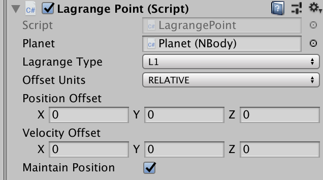
Planet: Indicates the planet with respect to which a Lagrange point is required. The planet is assumed to have an OrbitUniversal and the center body of this orbit is used by the component.
Lagrange Type: The type of Lagrange point.
Offset Units: Indicates if the position and velocity are relative to the system scale or in absolute units. If relative expressed as a fraction of the planet radius.
Position Offset: Offset from the exact Lagrange point for the object.
Velocity Offset: Offset from the exact Lagrange point velocity for the object.
Maintain Position: If unchecked, the object will be initialized at the indicated position and then will be left to evolve due to gravity. If checked the Lagrange position will be maintained and the object will be fixed in the rotating frame.
OrbitSimpleDecay
This script provides a simple per-frame reduction in velocity and results in the decay of an object in orbit.
Binary Orbit
Binary star systems are very common. Configuring a pair of objects in a specific orbit around the center of mass can require careful calculation of the initial velocities. The BinaryOrbit component handles this task and provides a scene view of the resulting orbits. It creates a zero-mass NBody object that is used to track the center of mass of the binary. This is used as the center point for orbit predictors to show the paths of the members of the binary.
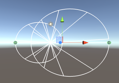
The BinaryOrbit component is added to a top-level game object and two “stars” are added as children. These stars each have an NBody component that describes their mass. By selecting the BinaryOrbit object in the scene view the orbits of the objects will be displayed and can be adjusted. GravityEngine provides a binary pair as a prefab object.
Velocity: Specifies the velocity of the center of mass of BinaryOrbit.
Ellipse Parameters: See the description of fields in OrbitUniversal above.
If the binary is to be in orbit around a third object an OrbitUniversal component can be added to the game object and configured in the usual way.
FixedObject
Adding a FixedObject component to an NBody game object creates an NBody object that has a mass but remains at a fixed position.
OrbitEllipse (deprecated)
OrbitUniversal with eccentricity < 1 is now the recommended component. For documentation see the 3.2 documentation.
OrbitHyper (deprecated)
OrbitUniversal with eccentricity > 1 is now the recommended component. For documentation see the 3.2 documentation.
BinaryPair (deprecated):
BinaryOrbit is now the recommended component.
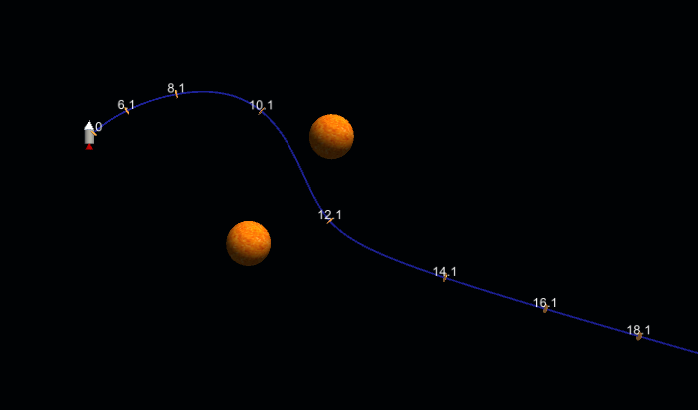
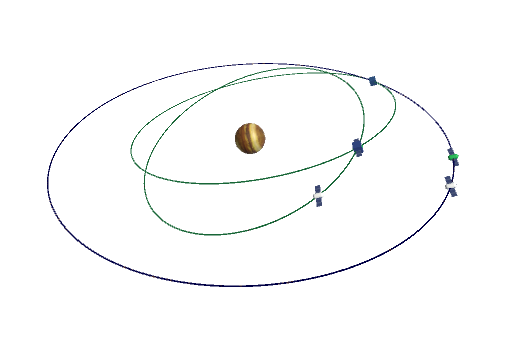
Trajectory Prediction
Gravity engine provides a facility to simulate the future paths of objects based on their nbody and Kepler evolution. GE implements this as a second copy of the gravity state. This state is evolved into the future for an amount specified in the GE inspector values when trajectory prediction is enabled. Once GE has evolved this far in the future then in the steady state it does a time evolution each step for both the current and future state of all objects. If an event in the present world state changes the velocity or position of a body, then the predicted evolution is no longer valid and GE needs to re-compute the future paths again. To allow control over this sudden CPU load this re-computation can be controlled using the “Re-computes per Frame” parameter in the GE inspector.
The future path of an nbody object is displayed by the addition of a trajectory component, typically as a child object to the nbody. Intercepts of trajectories can be found using the approach described below. Note this is most likely when orbits are in the same plane.
Trajectory Component
The Trajectory component shows the future path of an NBody object based on a simulation of the entire scene projected into the future. It handles cases where there are multiple massive objects interacting. It is more computationally intensive that an OrbitPredictor – which uses a two-body model of the interaction.
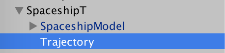
The Trajectory component works in conjunction with Trajectory configuration options in the Gravity Engine. It is attached to a *child* of an NBody object – since it requires a Line Renderer and material. Adding a Trajectory component will automatically add a Line Renderer component. In order to see the line in the scene a suitable material must also be added to the object.
The parameters for a Trajectory are:
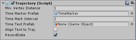
Min Vertex Distance: Minimum distance between positions required before a new point is added to the Line Renderer.
Max Points: Maximum number of points to be added to the Line Renderer.
Time Marker Prefab: A trajectory may optionally add an object at fixed time intervals along the trajectory. This element provides the prefab used. The objects added will be oriented so that the z-axis of the object is aligned with the path of the trajectory.
Time Mark Interval: The interval between time markers on the trajectory.
Time Text Prefab: A time label can be added to the time markers. This requires a prefab object containing a UI Text component. In addition the Canvas field in the Gravity Engine Trajectory configuration must be configured with a Canvas that has mode World View.
Align Text to Traj.: If checked the z-axis of the Text prefab will be aligned with the Trajectory.
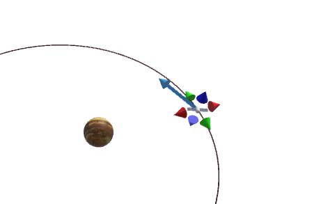
Trajectory Intercepts
If more than one object in a scene has a Trajectory component then GravityEngine can assess whether these trajectories will intersect at some future point. If there is such an intersection then there are components that can determine the required maneuver to make the first trajectory match the second trajectory from that point on. Note that in order for there to be a rendezvous, the trajectories must intercept at the same time world time. The trajectory intercept can determine both rendezvous and path crossing intercepts.
In order to determine a precise intercept maneuver the trajectory component attached to the objects must record data as their future path is calculated. The RecordData field in their Trajectory component must be set to true. This causes the position at each future frame to be recorded.
The TrajectoryIntercepts class (Scripts/Orbits/Transfers) makes use of this trajectory data to check for an intercept that meets the precision requirements set by the caller. A typical intercept determination is the MarkIntercepts method in the UserInterfaceRV script:
	/// Mark intercepts with the designated symbols and return a list of intercepts found
	/// for the predicted path of ship intersecting with the path of the target.
	private List MarkIntercepts(SpaceshipRV ship, SpaceshipRV target) {
                const float deltaDistance = 1f;
                const float deltaTime = 2f;
                const float rendezvousDT= 1f;
		trajIntercepts.spaceship = ship.GetTrajectory();
		trajIntercepts.target = target.GetTrajectory();
		trajIntercepts.ComputeAndMarkIntercepts(deltaDistance, deltaTime, rendezvousDT);
		intercepts = trajIntercepts.GetIntercepts();
		return intercepts;
	}
The above code uses ComputeAndMarkIntercepts() to determine if the two trajectories come within the specified distance and time of each other. The trajectory comparison checks for points that are within a specified distance from each other. Depending on the speed of the objects there may be many points that meet the intercept criteria. The parameter deltaTime is used to indicate over what time scale common intercept points should be considered duplicates. Finally the rendezvousDT parameter indicates the time precision required to declare the intercept a rendezvous (both arrived at the same time) versus a path crossing.
The TrajectoryIntercepts class creates a marker object at the position of the intercept, making it more visible in the scene. Prefabs must be provided for these markers.
Triggering Events: GETrigger
Some game events in GE need to occur when a specific physical condition is met. For example when a ship enter the sphere of influence of a moon, or when a ship reaches the point of closest approach to a moon. The GETrigger mechanism provides this capability.
GE ensures that the event occurs at the exact internal integration timestep where the condition is satisfied. This ensures that any maneuvers or course changes in the trigger code can use the most accurate data. The consequence of this accuracy is that trigger conditions are checked on every timestep. Trigger code that is CPU expensive (or that logs output) will degrade the game frame rate.
A trigger is added by instantiating a GETriggerManager.Trigger class and using ge.AddTrigger()
A trigger function implements the template function:
    public class Trigger
    {
        public Trigger(TriggerFunction f, System.Object data)
        {
            trigger = f;
            triggerData = data;
        }

        public TriggerFunction trigger;
        public System.Object triggerData;
    }
With a trigger function defined as:
public delegate bool TriggerFunction(GravityState gs, System.Object data);
This function returns true when the trigger condition has been met. GE then removes this from the list of active triggers. The triggerData is an opaque object that the trigger code can make reference to.
For example code that uses the trigger facility see the AngleTrigger in the TPIBurn.cs controller.
Maneuvers and Orbit Transfers
ManualShipControl
Interactive maneuvers via a click-and-drag interface is provided by the ManualShipControl script. Examples of the use of this script can be found in the In-Orbit: Manual scenes in the MiniGames folder. It provides clickable handles to adjust the ship velocity in 3D. Tutorial and detailed discussion.
Orbit Transfers: TransferShip
Orbit transfers assume that the spaceship is maneuvering in an environment with a single mass dominating the gravity in the scene. Orbit transfer calculations are done with respect to this central mass.
An orbit transfer is a series of maneuvers calculated to change the current orbit of an object to a desired orbit. This requires at least two maneuvers, the first to change to a path that intercepts the destination orbit and then a second maneuver to adjust the trajectory to match the destination orbit. Rendezvous transfers can require an additional maneuver to enter a phasing orbit.
The TransferShip component provides a single interface point to the main orbit transfer classes in GE. This script also provides a good example of how the underlying orbit transfer classes are used.
The common base class for transfers is OrbitTransfer. All orbit transfers extend this class. OrbitTransfer holds a reference of the from and to orbits and maintains a list of maneuvers required to implement the transfer.
Classes that extend OrbitTransfer are:
- HohmanGeneral: An all-in-one class to handle a transfer or rendezvous from any circular orbit to any circular orbit. This replaces the previous classes that did special cases (HohmannXfer, CircNonPlanarRendezvous, CircularInclination andAN, HohmannPlaneChange)
- Bi-Elliptic: Transfer from an inner circular orbit to a outer circular orbit via a three maneuver path that saves energy (but takes longer) than a Hohmann transfer. This orbit is only energy saving if the destination orbit has a radius more than 15 times the initial orbit radius. Can optionally control the axis of the transfer orbit.
- Circularize: A single maneuver to change the current orbit to a circular orbit.
- LambertUniversal: Implementation of a point to point transfer in a specified time. Algorithm is the best choice unless the source and destination points around the center are 180 degrees apart (the use LambertBattin)
- LambertBattin: A somewhat more computationally intensive Lambert transfer that works for all separation angles of source and destination.
- Patched Conic: Determine the correct maneuver to leave orbit from a planet and arrive at one of it’s moon. Augmented by the Lunar Course Correction feature.
Maneuver Component
Maneuvering a spaceship requires a series of course corrections scheduled to occur at precise future times in the game. To ensure the maneuvers are executed at as precise a physical time as possible, these are scheduled with the gravity engine. Maneuvers are executed by the engine at a time as close to the scheduled time as possible within the limits of the time step in use by the integrator.
A maneuver is specified by the Maneuver class. The key public values of a Maneuver are:
- nbody: the body the maneuver is to be applied to
- worldTime: The future GE world time at which the maneuver is to be executed
- mtype: (enum vector, scalar, setv) the type of maneuver:
- vector: apply the velChange vector to the NBody
- scalar: apply a velocity change of dV in the current direction of the Nbody
- setv: set the velocity to the value contained in velChange
- relativeTo: the NBody the maneuver is relative to. Transfer methods set this and ensure that maneuver is made relative to this body (which may have moved/changed direction since the time when the maneuver was determined).
- relativePos: if relative to is non-null, this field contains the relative position at the time of the maneuver
- label: a label assigned when the maneuver was created (transfer classes will fill this in)
The maneuver specifies a velocity change that is to occur at the maneuver time. A maneuver is added to the GravityEngine via the Gravity Engine AddManeuver() method. [There are also methods RemoveManeuver() and GetManeuvers()].
Commonly, maneuvers are set by code that has found a trajectory interception or an orbit transfer. Examples of both can be found in the UserInterfaceRV script used in the OrbitXfer Scene in Demos/MiniGames.
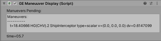
Debugging of maneuvers in the editor can be improved by attaching a GEManeuuverDisplay component in the scene. For example a pending final Hohmann transfer maneuver will appear as:
Maneuver Renderer
Visualizing maneuvers in the game scene can be an important game element. This is facilitated by the use of the ManeuverRenderer in conjunction with a script to configure the maneuver being considered. The ManeuverRenderer component is often added to the game object holding the scene controller. Examples can be found in the Lambert demo scenes.
An example of the components operation is:
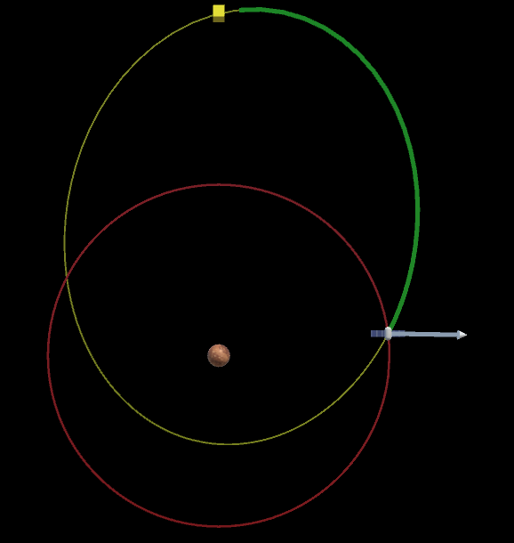
To configure this element:
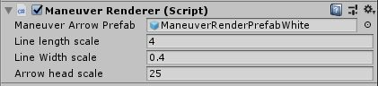
Manuever Arrow Prefab: A prefab containing a LineRenderer and a MeshRenderer (typically in child objects). See the examples ManeuverRenderPrefabWhite in the Prefabs folder.
Scaling: The remaining fields control the velocity dependent scale factors for the vector showing the maneuver. The line length, width and scale of the arrow head mesh can be tuned independently.
The maneuvers to be rendered are specified to the script by the ShowManeuvers() API call passing a list of Maneuver obects (as are returned by the orbit transfer scripts). For examples of this see e.g. the LambertDemoController script.
External Forces: Engines and Atmospheres
GEExternalAcceleration
External forces can be added to the GravityEngine simulations via components that implement the GEExternalAcceleration interface. This approach is used when the force needs to be applied to each physics integration step. If the force is a short duration or one-time correction, then the ApplyImpulse() method is a better choice.
Each NBody can have one component that implements GEExternalAcceleration. It is detected when the NBody is added to GE. This interface implements an acceleration method that will be called by the massive or massless integrator on every physics update. This can potentially become a performance concern. Attention to efficiency is recommended when implementing these components. The issue becomes more significant as time zoom is used and more physics steps per frame are run.
The single method defined by GEExternalAcceleration is:
double[] acceleration(double time, GravityState gravityState, ref double massKg);
where:
time: the time in GE internal units. This may be the current time (if the gravityState is the worldState) or some future time (if the gravityState is one for trajectory prediction)
gravityState: the GravityState being evolved. (Can be compared with GE.GetWorldState() to determine if it is the current state vs a trajectory state)
massKg: (ref) Used to pass back the current mass. This is typically used by e.g. the EarthRocket component that uses this to determine the current mass of the rocket to include in air resistance calculations using EarthAtmosphere.
Rocket Engines
Rocket engines provide continuous thrust of a massless NBody in the scene. To make use of a Rocket Engine a script extending the RocketEngine class is attached to the NBody. Two implementations are provided in GE 1.6:
- OneStageEngine
- MultiStageEngine
These engines provide an inspector panel to define the mass of the spaceship, fuel and thrust.
GE provides trajectory prediction for powered flight (if GE trajectory prediction is enabled).
The inspector panel for the MultiStageRocket is:

The units for mass, thrust and time are kg/N/sec. respectively. These are adapted to the chosen Gravity Engine unit system internally. The values in this example roughly correspond to those of a SpaceX Falcon9 rocket.
The implementation of a rocket engine class hinges on an implementation of the acceleration function (link to doxygen). This function is used on every integration time step to ensure a smooth, continuous path. This is the best method to ensure accurate simulation of the flight. Note that to optimize the integration code this function is only called from the MasslessBodyEngine; the efficiency of the evolution of masses in the scene will not be affected by rocket engines.
The MultiStageEngine is used in the Demos/MiniGames/LaunchOrbit scene. A code example for triggering a stage separation can be found in the DropStage() function in LaunchUI.cs (Scripts/Samples/Launch/LaunchUI.cs).
Earth Atmosphere
The EarthAtmosphere component computes the air resistance based on air density ay a specific height, mass and velocity. It can be attached directly to an NBody or may be used in combination with a rocket element. In this case, since only one GEExternalAcceleration is allowed per NBody, a unifying component e.g. EarthRocket is used to combine the acceleration of the rocket and the effect or air resistance.
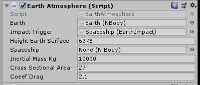
Earth: The NBody object that represents the Earth.
Impact Trigger: (Optional) An object with a component that implements the ImpactTrigger abstract class. The method Impact() will be called when the height of the spaceship is less than the height of the Earths surface. Typically this script will Inactivate or Remove the spaceship from GE. See the EarthImpact class for an example implementation.
Height Earth Surface: The height of the Earth surface. The scene uses Orbital units in GE, hence this value is in km.
Spaceship: (optional, if not specified the attached NBody will be assumed). The spaceship object to apply atmosphere resistance to.
Inertial Mass kg: The inertial mass of the spaceship in kg. This is used in the determination of the acceleration due to air resistance.
Cross Sectional Area: The cross sectional area in m^2 of the spaceship. In general this will vary based on the object orientation and could be updated based on that by a user provided script.
Coeef Drag: The co-efficient of drag. A dimensionless number that represents the resistance of the object based on its shape. Typically a number in the range of 2.0-2.3 (for a sphere it is about 2.1)
Gravitational Particles
Gravity Particles
Adding a GravityParticles component to a Unity particle system will allow the GravityEngine to move the particles according to the gravity of all objects in the scene. The particles will be treated as massless bodies and evolved using a Leapfrog algorithm.
Particle creation can be done by the Unity particle system component or can be over-ridden by adding a component that implements the IGravityParticlesInit interface (scripts DustBall, DustBox and DustRing demonstrate how this is used).
The particle system must operate in World Space. This particle system attribute will be changed automatically (and a Warning issued) if it is set to local.
Scenes with large numbers of GravityParticles can require more from the CPU. Care must be taken when adding large numbers of particles to ensure game performance is still acceptable. Reducing the steps per frame for Particles in the GravityEngine may also be useful.
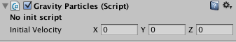
Initial Velocity: The initial velocity to be added to all particles from the particle system on creation. This option only appears if there is no init script attached to the component.
Dust Ball
DustBall implements IGravityParticlesInit and is used to initialize a sphere of particles all moving at the same velocity.
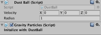
Velocity: Initial velocity of the particles in the dust ball.
Radius: Radius of the dust ball.
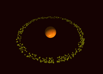
DustOrbit
Particles in an orbit are generated with the DustOrbit component. The width of the particle ring (as a percentage of the semi-parameter) is controlled by a parameter in the DustOrbit. This component will automatically add an OrbitUniversal component and this is used to control the parameters of the orbit the particles will be placed in. The particles are generated at random phases in the orbit.
Dust Ring (deprecated)
This script initializes a ring of particles around an NBody object. It has been superseded by DustOrbit.
The shape and orientation of the ring are controlled in the same way as an OrbitEllipse object.
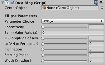
Ellipse Parameters: See the description under OrbitEllipse, above.
Width: Defines the width of the particle ring as a percentage of the radius.
Dust Box
Initializes particles in a 3D box.
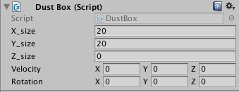
X_size/Y_size/Z_size: Size of the X, Y and Z axes of the box. Box will be centered at the transform position.
Velocity: Initial velocity of dust particles
Rotation: 3D rotation of the dust box. (Rotation must be controlled here and not in the game object transform to ensure correct rendering by the GravityEngine).
ExplosionFromNBody
ExplosionFromNBody creates a cone of particles that ‘explode’ away from an NBody object. It determines the required velocity to escape the gravitational field of the NBody such the particles reach a specified distance from the body.
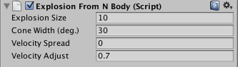
Explosion Size/Velocity Adjust: The maximum distance the explosion particles should travel before falling back to the NBody on which the explosion is occurring.
The size is used to determine the initial velocity of the explosion. In cases where there is a large initial velocity due to a massive NBody or small radius, the first integration step may move the particles too far. This will result in the size being exceeded. The Velocity Adjust field can be used to “tune down” the initial velocity. Typically values in the range of 0.7-0.9 are useful.
Cone Width: Defines the width of the ejection cone in degrees (from center axis to outside).
Velocity Spread: The variation in the velocity applied to the particles. The value used in the standard deviation around the velocity required to obtain the indicated size. A value of 0 will ensure all particles start at the same speed, larger values will give a wider range of velocities resulting in a more spread out value.
This component is usually triggered by a collision between NBody objects.
Collisions
GravityEngine relies on the Unity collider components to detect collisions via trigger events. It does not make use of them to handle the physics of the collisions.
NBodyCollision
NBodyCollision is attached to the CHILD of an NBody object. It is typically attached to a MeshFilter object with a Collider and Rigid Body attached. The Collider/Rigid body configuration must be:
- Collider IsTrigger Enabled
- Rigid Body IsKinematic Enabled
- Rigid Body Mass set to 0 (will appear as a very small number in inspector)
- RigidBody UseGravity Disabled
The NBodyCollision object will handle the trigger events from the collider and interact with the GravityEngine to achieve the desired outcome.
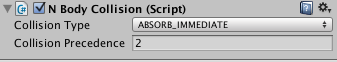
Collision Type: Defines how the collision should be handled. One of:
ABSORB_IMMEDIATE: On trigger detection the object and its NBody parent will be removed from the scene. The parent NBody’s momentum will be added to the body that it made contact with.
ABSORB_ENVELOP: Once the body with this component has completely entered the other body (based on sphere sizes) the object and NBody parent will be removed from the scene. The parent NBody’s momentum will be added to the body that it made contact with. Envelop works reliably only when the sizes of the objects are different.
EXPLODE: On contact the object and NBody parent will be removed and a particle explosion will be triggered. When selected this element requires an additional parameter: Explosion Prefab
BOUNCE: On contact the parent NBody will reverse direction (as will the parent NBody of the object it made contact with). When selected a Bounce Parameter is displayed. This is value in the range 0..1 with 1 indicating a no energy loss full bounce.
EXPLODE_OR_BOUNCE: Based on contact velocity either explode or bounce.
Collision Precedence: In cases where two bodies with NBodyCollision scripts collide, one must take precedence. The body with the lower precedence will be run. If the precedences of the objects are equal, the Unity game object unique id is used to break the tie.
Floating Origin/Origin Relocation
Gravity Engine provides two mechanisms for moving all the objects under it’s control.
Use Transform to Reposition
The GE inspector contains a checkbox “Use Transform to Reposition”. When active the GE apply the position, scale and rotation of the transform of the GE to all objects before rendering them to the scene. This allows the entire GE universe to be repositioned and scaled in the scene. For example, the Demos/Reposition scene show a small solar system set on top of a cube as in a museum exhibiit.
NOTE: internally the physics evolution is not affected by the GE transform value.
MoveAll()
In cases of a spaceship flying through a large scale universe it can be awkward to have the spaceship at large values in position space and in some cases leads to artifacts as e.g. a spaceship at large values moves near other objects. Numerical “jitter” in these large values can cause visual jitter in the game. A common solution to this issue is to re-center the physics values of the spaceship in the scene, so that it does not exceed some modest limit (typically thousands of position units).
Re-locating all the internal physics values for objects can be accomplished with the MoveAll() GE method. As an example see the scene Demos/MoveAll. The MoveToDemo.cs sample code shows how to use this. Note that in addition to centering the spaceship it moves the camera to track the change in position as well. Since the objects jump to their new position and trail renderers will show the move. If a scene uses trail renderers then their points must be adjusted by the game code.
System Builders
Solar System
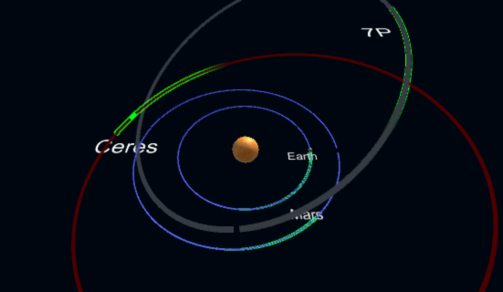
Scenes with planets, comets and asteroids can be created using the SolarSystem component. A prefab of this object is provided in the Prefabs/SolarSystem folder.
The Solar System component is interactive and provides an “Add Body” button to start a dialog to allow the developer to select the object type (Planet/Asteroid/Comet) and the specific object. If the object is not in the database provided there is an option to open the Jet Propulsion Lab/NASA database in a browser so the desired object can be found. The orbital parameters for the object can then be pasted into the object creation dialog. The JPL/NASA database lists all known comets and asteroids – over 500,000 objects in total!
When using the Solar System builder the unit system in the Gravity Engine must be set to SOLAR. This selects units of AU, 1E24kg and year. The Solar System inspector allows the start date to be specified and the objects will be moved to the position corresponding to that date.
The scale of the planets is centrally controlled from the Solar System builder to allow the planet scale to be changed maintaining the relative sizes of the planets. The choice of scale in the solar system is challenging if the goal is to show the entire solar system. Mercury orbits every 88 days and Neptune orbits in 165 years. The physical scale is similarly challenging. Often it may be necessary to have different scenes for inner and outer planets.
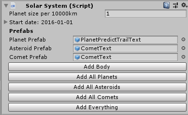
PLANET SIZE PER 10,000 km: Sets the number of Unity length units per 10,000 km of planet radius. For reference, Earth has a radius of 6378 km, Jupiter 71,492 km.
START DATE: Specify the start date for the solar system. This will modify the positions of the bodies in the scene.
PREFABS: When bodies are added they are constructed from the prefab of the corresponding type. The prefab objects must contain NBody, OrbitEllipse and SolarBody components (SolarBody is used to hold the reference values of the orbit prior to scaling).
The Prefab may optionally contain a child with a Text component. If present the SolarSystem will insert the object name when the object is created. If the solar system is then made a child of a World UI Canvas then these text labels will be visible.
ADD BODY: Open a dialog to add a body to the scene. The Add Body dialog will appear:
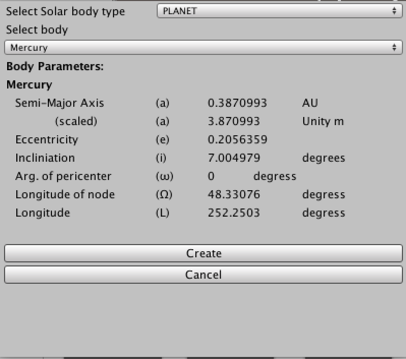
The type of body is selected by the first selection box. Each of PLANET/ASTEROID/COMET provides a selection box of well know celestial objects. If the desired object is not on these lists then the JPL_ASTEROID/JPL_COMET modes allow the parameters for a body to be located in the NASA/JPL database and then pasted into the dialog.
RandomPlanets
The RandomPlanets script is used to create a system of planets in random orbits around a central body when the scene starts. It allows control of the number of planets and a range for each of the orbital parameters. In order to allow more than one planet game object type it allows a list of planet prefabs to be provided and will pick randomly from the list for each planet creation.
This script is also a useful example demonstrating how to procedurally create and link planets.
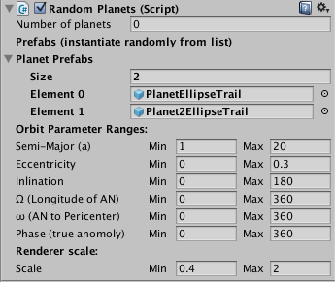
Number of Planets: The number of planets to be generated
Planet Prefabs: A list of prefab objects that will be used to create the planets. The prefab planet structure must match the examples in the prefab folder:
- Base game object with an NBody and OrbitEllipse component
- A child game object with a MeshRenderer to display to model for the planet.
Orbit Parameter Ranges: Min/Max ranges to be used for each of the orbital parameters of the planets.
Renderer Scale: Min/Max range of the local scale to be applied to the models of the planets as they are created.
Scripting Interface
Scene setup can also be done under script control. Documentation for the script interaction in HTML and can be found in html/index.html.
ThreeBodySolution
The gravitational interaction between three equal-mass bodies is a long-standing area of investigation in celestial mechanics. Over the past three hundred years a variety of solutions have been found. The Gravity Engine asset provides a set of these solutions, coupled with a special algorithm to allow them to evolve through regions where the bodies come very close to each other.
These solutions can be explored using the ThreeBodySolution script. They can also be found in the app ThreeBody available on iOS and Android. (The Gravity Engine asset derives from the work done on ThreeBody).
This component is added to a top-level game object in the scene. (Typically it is added to the GravityEngine game object).
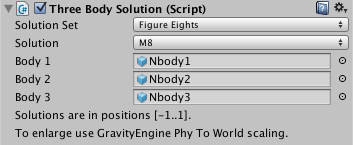
Solution Set: Name of the solution set to select a specific solution from.
Solution: Name of the solution from within the solution
Body1/2/3: Nbody objects with mass 1 to be used in the scene. Their positions and initial velocities will be initialized based on the solution that has been selected when the scene starts.
Modifying the Gravitational Force

The GravityEngine class allows for the force between masses to be changed – allowing the game developer to explore universes with non-standard physics. This can be done by selecting a different FORCE under the Advanced tab in the GravityEngine inspector. There are a number of built-in alternatives (the function of distance is indicated in parenthesis):
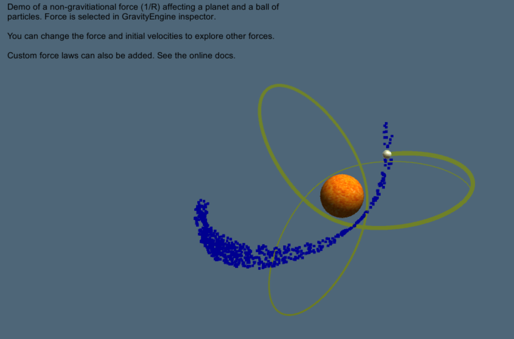
- InverseR (1/R)
- InverseR3 (1/R^3)
- ForceR (R)
- ForceR2 (R^2)
- Custom (requires a class attaching the force delegate interface be attached to the GE object).
The usual closed orbits that arise due to gravity are special. An object in a gravitational orbit returns to where it started from after one orbit. For other forces this is not true (with the exception of R^2) and the orbit will instead form a “spirograph” type pattern, the details of which depend on the force law. In reality in close proximity to a large mass the same effect happens in the real world – an effect due general relativistic effects. Famously, the orbit of Mercury when measured over decades is not exactly closed.
If the force is changed to something non-standard then the built-in orbit tools (OrbitEllipse, OrbitHyper, BinaryPair) will not show the correct paths. They determine paths with a the standard equations of gravity.
Non-Spherical Source: J2Gravity
GE can be configured to model non-spherical sources with a dipole (J2) model of the oblateness. This is done by setting the Force entry in the GE inspector (under Advanced) to Custom and attaching a J2Gravity script to the object holding the GE component. The individual non-spherical planets can now add a J2ForceData component. For example, for the Earth add to the object with the NBody the component:
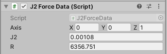
The fields defines the rotational axis, dimensionless number J2 that specifies the degree of oblateness and the radius of the planet. When GE performs force calculations for an NBody with this component it will use a model for the non-spherical dipole field.
For an example of this see the EarthWithJ2_SunSynch field. This scene demonstrates how the oblate Earth results in a precession of the ascending node at the same rate the planet orbits the sun.
Defining a New Force
To define a new force requires a class inheriting MonoBehaviour and implementing the IForceDelegate interface. This interface requires that the force law and (optionally) it’s derivative be provided as methods:
- calcF(double R) force function in terms of R only
- calcFdot(double R) derivative of force with respect to R. This is optional. It is used if the Hermite integrator is selected. [To calculate derivatives symbolically you can use one of many online tools found on the web]
This class must then be attached to the same game objects as the GravityEngine script and the Force must be chosen as Custom.
Scaling
Gravity is a force described by Newton’s gravitational law:

Using F = ma and solving for the acceleration of mass 1 the acceleration is a function of mass (m_2), distance (r) and Newton’s constant G.
Consider the effect that a change of distance scale has in this formula. If a scene is rescaled to a distance 10x smaller, the acceleration experienced by bodies will be a factor of 100x smaller. This will result in e.g. different orbit periods and significant changes in things actions such as orbit transfers.
Gravity engine provides the ability to rescale game scenes without changing the physics of the scene by using GE parameters that define the lengthScale and timeScale (when the units are orbital, solar or SI) or massScale when dimensionless units are used.
During setup GE determines a mass scale for the scene based on the units and the length and time scales defined in the GE inspector. This mass scale is applied to ever massive object as it is added to GE. To give a simple example, in SI units (meters/kilograms/seconds) and a length scale and timescale of 1 the mass scale will be the value of G given in SI units. Depending on the units and length/time scales this value will be adjusted as required to maintain the same physics in the scene.
In the case of dimensionless units, G=1 is assumed and the mass scale can be controlled directly in the GE inspector. As a simple rule, increasing the mass scale will make orbits faster. The relationship is not 1-1 since the orbit period is a a function of 1/sqrt(mass). Doubling the mass will result in an orbit period about 70% of the previous value.
This scaling is handled by the GravityScaler class.
Performance
The following performance results are from running as a Unity application under Windows 10 on a system with an i5-7500 at 3.4 GHz with 16GB RAM and a GTX1070.
| Scenario | Number of Bodies |
|---|---|
| Massive bodies | 225 |
| Massless Bodies | 1604 |
| Massless with OrbitPredictors | 569 |
| Massless with OrbitRenderer | 712 |