Scene Components#
Controllers#
GSController#
GSController is responsible for:
creating an instance of
GravityEngine(GE)detecting the bodies to be added to the GE
detecting the display controllers that will coordinate displaying of those bodies that have display components attached
evolving the GE system based on Update() and potentially LateUpdate() Unity callbacks
There can be multiple instances of this class in the scene and they will all operate independently.
The inspector view is:
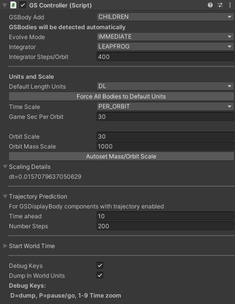
GSBody Add: This determines which GSBody components are to be added to this controller on scene start.
CHILDREN: Find all
GSBodycomponents in the hierarchy below this objectLIST: Provide an explicit list of
GSBodyobjects in the inspector. When selected the inspector will provide a field to listGSBodyscene elementsSCENE: Scan the entire scene for
GSBodycomponents
Evolve Mode: The internal evolution used by the underlying GravityEngine. The key distinction is that immediate
mode runs the GE physics loop as part of the GSController update cycle. This means that all GE API calls can be used
at any point in other scripts. The use a job mode means that the GSController update will schedule the physics job during
Update() and then ask for the job to complete in LateUpdate(). GravityEngine will not allow direct API interaction if
a job is running in the background and instead interaction is done by requesting a callback on the completion of the
physics job via GravityEngine.PhyLoopCompleteCallbackAdd().
(Note that I expect to develop a mode that runs the job from one Update() cycle to the next frame Update() in a later release).
The modes are:
IMMEDIATE: Run physics (and particles if present) in the
GSControllerupdate loop. Allows direct GE API useIJOB_LATEUPDATE: Schedule physics core as a Job in Update. Complete in LateUpdate(). Requires GE interactions via callbacks since the physics core is running in parallel with other user Update() functions.
IJOB_FRAME: Schedule the physics core in LateUPdate() and complete in the Update() of the next frame. The intent is to set the script execution order (Edit/Project Settings/Script Execution) so that the
GSControllerUpdate() runs before all other user scripts. This ensures the physics core has completed and allows all user scripts to directly access state without callbacks.
Integrator: N-body evolution (GRAVITY mode in GSBody) requires numerical integration of the forces. This is the core of
the physics engine. The precision of the simulation is highly dependent on the choice of the integration method and the
selection of timestep and scaling.
LEAPFROG: Use first order Leapfrog/Verlet. Very efficient and conserves energy well.
RK4: Fourth order Runge-Kutta. The workhorse method in the numerical differential equation world. Does more computations per time step that Leapfrog
Integrator Steps/Orbit: The number of steps the integrator should take for the reference orbit described by the orbit mass scale and orbit length scale below. 200 steps is a reasonable default for orbits that are not highly eccentric. If the resulting time step is longer than the typical time per frame (scaled appropriately) then the timestep will be made smaller resulting in more steps per orbit than specified here.
Default Length Units: The choice of world units for the GSController and the units in which most GE API calls will return values (the exception being recorded output).
See scaling
Force All Bodies to Default Units Button: This button switches all GSBody objects under control of this GSController to the default units set in this controller.
Game Sec Per Orbit: For the specified orbit scale and mass adjust the run time scaling so that one orbit takes this long.
Orbit Scale: The size of a typical orbit in the scene in the default units.
Orbit Mass Scale: The mass of the central body for a typical orbit. Generally the mass of the heaviest object in the scene.
Autoset Orbit/Mass Scale Button: This button will scan the GSBody objects that are set to be part of this controller and determine
the maximum mass in the collection and an average orbit distance.
Scaling Details (Foldout): Shows the value of dt that was determined based on the default scaling and game sec per orbit.
Trajectory Prediction (Foldout)
See Trajectories for an overview of this feature. GSDisplayBody components may elect to have a future
projection path plotted with a LineRenderer. This is generally used when N-body motion is happening and a simple orbit
extrapolation with GSDisplayOrbit is not sufficiently accurate due to the effects of other masses.
Time Ahead: The world time interval for which a trajectory will evolved into the future.
Number of Steps: The number of steps used in recording each future trajectory.
Circular Three Body System (Foldout) Setup information for a circular restricted three-body system. See Circular Three Body Systems.
Start World Time (Foldout) These field specify the start world time. This is optional and is used when either:
there are orbits initialized with two-line element information (embedded in this info is a time at which the info is valid)
orbits have been build with the solar system builder with orbit elements defined at a specific time
The start time must be set to a value equal or later than the latest time in any of the GSBody components. (This is because
e.g. the SGP4 propagator cannot compute times before the TLE start time). This can be done automatically by using the utility
button to scan for the latest TLE start time and set the GSC time accordingly.
An editor button can be used to set the start time based on the current time or to the time of the latest SGP4 TLE initialized body in the scene.
Debug Keys: When enabled the controller will check for specific key presses during the Update() phase:
D: dump the internal GE state to the console (implemented as a callback so will get a coherent dump in job mode)
P: pause/go the execution of GE
1-9: adjust the amount of world time evolved for each game second. The zoom factors are (1-9):
1f, 2f, 3f, 4f, 5f, 10f, 20f, 50f, 100f.
GSDisplay#
The display of objects, orbit paths and trajectories is handled by the GSDisplay component. It detects (or is given) a set of objects that
implement the GSDisplayObject base class. Most commonly this will be GSDisplayBody and GSDisplayOrbit components. The display bodies will
typically have some graphics object (a sphere or mesh) that will show the body in the scene.
There can multiple instances of display controllers and more than one display body to represent a GSBody in a GSController. This allows e.g.
a mini-map to be displayed.
The origin of the displayed system is the transform position of the GSDisplay and the rotation will adjust the overall rotation. The scale of the
transform will not adjust the scale, this is done by a specific field in the GSDisplay inspector. The scale used in the component is the
factor used to map from the default world space units specified in the GSController to position values of the display objects (e.g. GSDisplayBody).
GSDisplay does provide a tool to set this value automatically once the scene has been configured with GSBody objects.
The GSDisplay inspector view is:
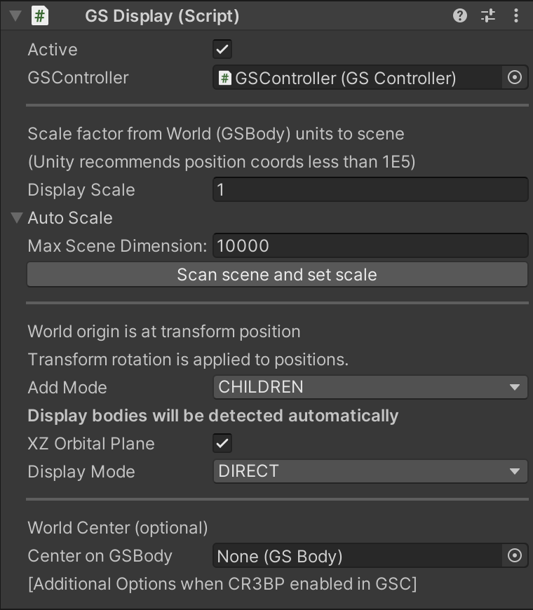
Active When true, this component will display the display objects it is responsible for.
GSController The GSController that is controlling the bodies to be displayed. If the controller is the parent this will be detected automatically.
Display Scale the scale factor to apply to the position in world units to be used for display of body positions and orbits. As a general rule Unity
prefers position values of less than 1E5 units in the transform of a game object. Values beyond this will generate warnings.
Auto Scale Foldout Display scaling is intended to limit the maximum transform position to something “reasonable” in the context of the game scene. This may be a few hundred position units or up to the Unity soft limit of 100,000. In dimensionless units this may be a simple factor (even 1.0) but when more real-world units (Earth orbits, solar system) are defined determining a reasonable value gets more complicated. The “Scan Scene and Set Scale” button helps.
Max Scene Dimension Defines the scene distance to be used for the object in world space with the largest position value
Scan Scene and Set Scale (button) Computes a display scale value and fills in the field. This operates by asking the associated
GSController for the initial position of each body that will be displayed by this component. The maximum value is then divided by the
maximum scene dimension to determine a scale factor.
AddMode Determines how the display objects under the control of this GSDisplay will be found
CHILDREN: Find all objects that are attached to children of the
GSDisplaycomponentLIST: Use the list of objects provided (a list entry will appear when this is selected)
SCENE: scan the scene for all objects extending
GSDisplayObject
XZ Orbital Plane Locate orbits in the Unity XZ plane. This results in the display coordinates of an object at world position \((x, y, z)\) to be displayed at \((x, z, y)\). This shift from the right-handed physics coordinate system to Unity’s left-handed coordinate system make the orbits match the usual form with respect to rotation directions and ascending/descending node positions. See RH vs LH Coordinates.
Display Mode
DIRECT: Show the current scaled positions from the GE. Note that due to numerical step size this may jitter ahead or behind of the elapsed game time by a small amount.
INTERPOLATE: Adjust the displayed positions by interpolating the position to the exact game time based on the given velocity.
World Center
This optional field allows the display controller to center the scene on a position of a specific GSBody. This can be useful to maintain the player ship
at the origin and to give all other scene objects a position and velocity relative to the ship.
Maintain CoRo When the GSController reference frame has been set to the corotating frame the GSDisplay component may elect to display the system in
a reference frame that co-rotates (so that e.g the moon in an Earth-Moon system does not appear to move in the scene because the view rotates along with it).
Per Body Elements: GSBody#
The GSBody component is the component that describes a body that will be evolved using GE2. As a result it contains a lot of details. The overall inpsector view is show below.
Each section is then described in further detail below.
GSBody is a key scene component used to describe a body that GravityEngine will evolve according to N-body physics or under the control of a
specific propagator. It allows for the initial conditions of the body to be specified in a variety of ways:
absolute position and velocity
position and velocity relative to another
GSBodyorbital elements with respect to another
GSBodyfixed in the scene
Earth satellite two-line element state information (from e.g. celestrak.org)
‘GSBody` also describes how GE is to evolve the body, see the description of ‘Propagator’ below.
The first two inspector fields are common to all input formats:
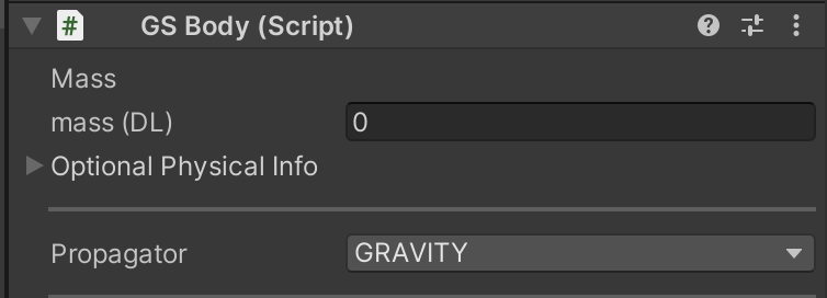
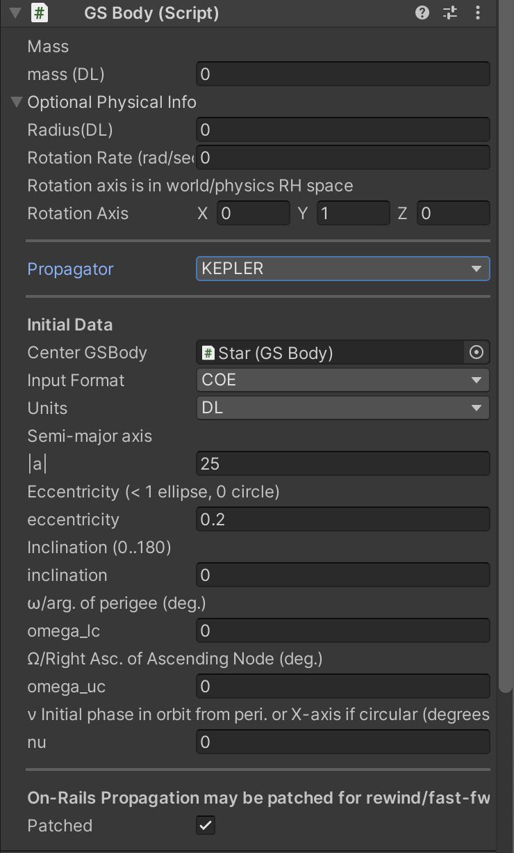
Mass: The mass of the object. In dimensionless units this value is arbitrary and only it’s value relative to other bodies is important. In dimension-full units this is in kilograms and typically very large (e.g. Earth is of order E24 kg).
Spaceships and satellites are typically given zero mass since they have no appreciable effect on e.g. the Earth they are orbiting. Massless objects are maintained
separately in GravityEngine since these objects do not affect others the force they impart on other bodies can be skipped resulting in less CPU use. Note that
in an N-body system the massive interactions grow as \(N^2\). The smaller the number of massive objects, the better.
Propagator:
GRAVITY: Evolve using N-body Newtonian gravitation i.e. “normal gravity”
KEPLER: Evolve deterministically along a conic around a specified central body using Kepler’s equation
PKEPLER: Evolve deterministically along a conic around the Earth modelling the J2 non-spherical Earth and optionally adding drag
SGP4_RAILS: Evolve using the SGP4 Earth satellite propagator. This propagator includes J2, atmosphere and effects of the moon and sun for larger orbits.
FIXED: Maintain the body in a fixed position.
EPHEMERIS: Evolve the body according to a table of R, V values for specific times, interpolating as required.
PLANET_SURFACE: Fix the body at a specific point on the surface of body. The center body radius and rotation rate must be specified. Optionally, the initial position based on GSController world time can be used to orient the Earth in an Earth-centered inertial frame. See planet surface
KEPLER_COE:
UNASSIGNED: No choice made. Will result in an error when scene is played.
Early Propagation
Three propagators have the option to compute positions for times before the time value they are initialized at: KEPLER_COE, PKEPLER and SGP4_RAILS. The common
use case is to add bodies at some time t and then evolve them into the future. In scenes where all bodies have been added with an on-rails propagator it is
possible to rewind the time to earlier values. These values could potentially be times before a body was added. Depending on the GSBody the scenario might
chose to allow the position to computed as usual at the earlier time, hold the position at the initial position added or generate an event and remove the
body from physics evolution. The value of this field (when a suitable propagator has been selected) defines which behaviour will result in this case.
There are several inspector views depending on the input format selected. Several of them are shown below. Before describing them we describe the remaining common input field: Patched.
Optional Physical Info
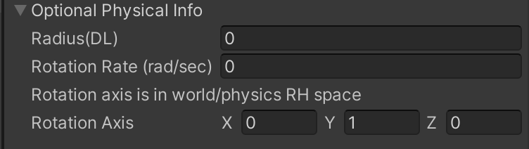
The optional foldout “Optional Physical Info” provides a place to specify some physical attributes of celestial bodies that may be useful
to the display and game code. (If the SolarSystemBuilder is used, this information will be filled in when the values are known to the JPL Horions database).
The radius of the objects (in GSBody default units) can be specified.
Information on the rotation of the body can also be specified by providing the rotation rate (in radians/world seconds) and the rotation axis.
Patched: A body may elect to use some of the on-rails propagators (most commonly KEPLER) in patched mode.
RV Initial Data#
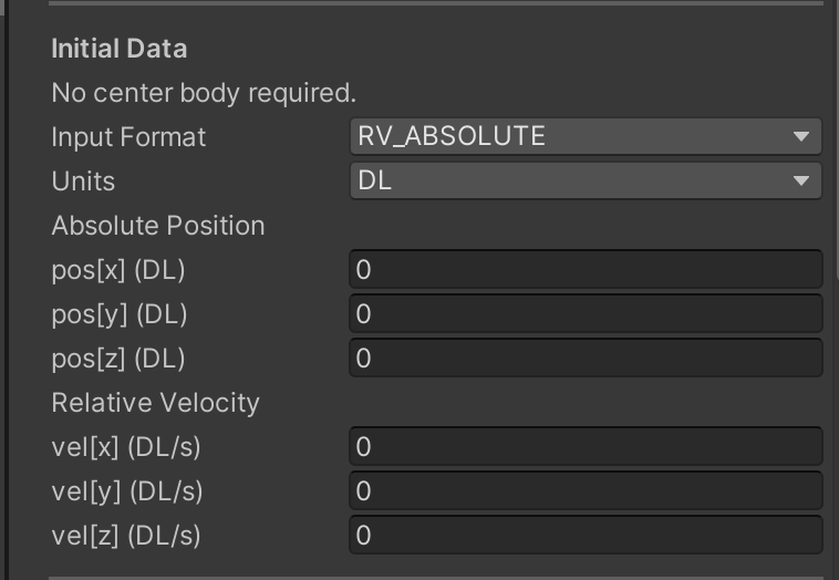
The inspector fields for the RV data are simple double fields for the values of the position and velocity vector in the specified units.
These values may be given in absolute terms or relative to some other GSBody.
Orbit Initial Data#
A body in orbit around another body can be specified by providing the classical orbital elements (COE) or minor variations in which instead of specifying the semi-major axis size, the apoapsis/periapsis (for Earth this would apogee/perigee) can be provided. A separate option exists for specifying a hyperbola where only the periapsis is required.
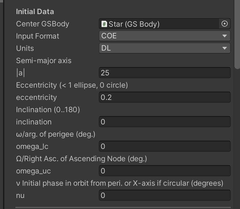
The orbital elements divide into the those describing size/shape and orientation. See FIG XX.
Semi-Major Axis: (size) indicates the size from the true center of an ellipse to the farthest point.
Eccentricity (e): The shape of the orbit. Closed orbits (\((e < 1)\)) are circular when \(e=0\) and more elongated as \(e\) gets close to \(1\). Orbits with \(e > 1\) are hyperbolas and the COE_HYPERBOLA input mode is a better choice.
The next parameters relate to the orientation of the orbit in space.
Inclination (i):
OmegaU/RAAN (\(\Omega\)):
OmegaL/Argument of Periapsis (\(\omega\)):
True Anomaly (\(\nu\)):
An alternative to defining the shape and size with (\(a, e\)) is to use the periapsis and apoapsis. This can be done by selecting COE_ApoPeri as the input mode.
Two Line Element#
For Earth satellites on-line databases provide state information at a given time (also referred to as epoch). Historically these were “computer card friendly” so they are formatted in a somewhat odd two line, 80 character format. For example from Celestrak.org for the International Space Station
ISS (ZARYA)
1 25544U 98067A   24011.38118347  .00015819  00000+0  28198-3 0  9997
2 25544  51.6404  17.2554 0003852  20.7619 339.3526 15.50260516434080
This can be pasted directly into the text field when the SGP4_ONRAILS input mode is selected.
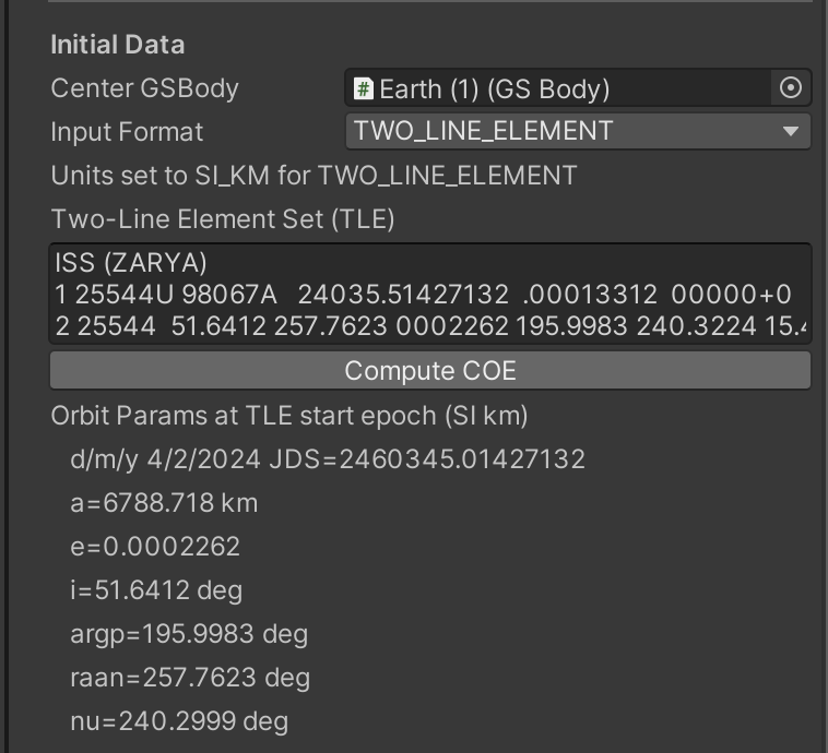
Note the use of this input format assumes the scene has an Earth with the correct mass (it will check and warn you if not) and some form of
units other that DIMENSIONLESS has been selected.
Ephemeris#
The path of a body can be directed from a file providing a CSV table of values of the form \((t, r_x, r_y, r_z, v_x, v_y, v_z)\). When the Ephemeris propagator is selected the initial data for the body will come from the ephemeris file and is not configurable in the inspector.
The .txt file should be placed in a Resources folder somewhere within the project and then the name of the resource (without the .txt extension) is provided in the inspector field.
A toggle box also indicates if the positions are relative to some center body or are absolute world position units.
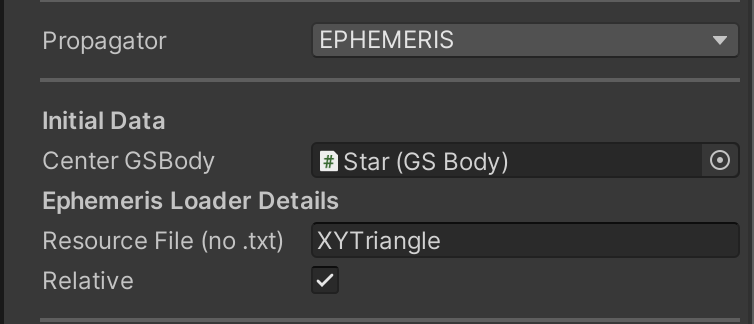
An example of this operation can be found in the going further sample Ephemeris.
Latitude/Logitude Position#
Initial position can be specified on the surface of planet using latitude and logitude. If the Position Type is set to EARTH_SURFACE then a selection of pre-specified launch sites (e.g. Kennedy, Vandenberg) can be chosen.
This initial data requires that the optional physical information for the body be initialized because it requires the planet radius.
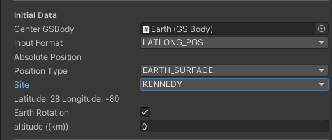
Center GSBody: A reference to the GSBody for the planet on which this body is located.
Position Type: CUSTOM or EARTH_SURFACE
Site: For EARTH_SURFACE a list of possible launch sites.
Latitude/Longitude: For CUSTOM the vaolue in degress for lattitude and longitude
Earth Rotation: If selected, determine the launch site on a rotating Earth based on the GSController start date and time plus the elapsed time at the time the body is added. This assumes an inertial Earth reference frame (ECIF).
Altitude: Height above the mean radius of the planet. (Note that when displayed on a Unity sphere the body may appear to “float”. This is because in the polygon representation of the sphere only the vertices are at the exact radius of the sphere).
Epoch Time#
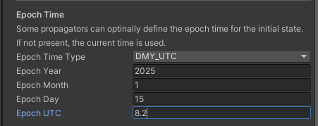
Orbital element initial data (COE and TLE) define a specific state of the body in orbit around a central body. In cases where this orbital information is taken from the real-world it will be defined a specific time. For example
the TLE for the Internation Space Station will define the orbital state at the time it was measured. Data from the JPL solar system database will define a position of a planet or moon at a particular time. The epoch time
GSBody input parameters define the time at which the state is defined. Recall that the time of the system is set in the GSController editor (when non-DL units are used). GE2 manages the state and ensures that when the
GSController starts the epoch time of the state is consulted and the bodies position and velocity is adjusted to align with the current controller world time. There are two cases to consider:
The epoch time of a body may be earlier than the controller start time. In this case
GECorewill evolve the body forwards in time to the controller start time. (This requires the propagator allow this kind of “on-rails” evolution i.e. isKEPLER,KEPLER_COE,PKEPLERorSGP4_RAILS)The epoch time is later than the controller start time. In this case the body must have an on-rails propagator that allows early propagation and have this early propagation mode enabled. The propagator can be
KEPLER_COE,PKEPLERorSGP4_RAILS.
The epoch time can be specified as world seconds, DMY or Julian data.
If the input format is a two-line element (TLE) the epoch time is embedded in the TLE and will be displayed here. If a user wishes to over-ride the TLE value this can be done by deselecting the “Use TLE Epoch” checkbox.
Display Objects#
The display of GE2 objects is controlled by a separate component than the component describing their initial conditions and propagation. This allows decoupling of display and evolution allowing e.g.
zoomed in views to select only the bodies of interest to render. For example, if zoomed in on Jupiter and its moon, there is little point in displaying Mercury in the scene.
multiple display views of the same objects, with different visual representations e.g. a mini-map with labels and dots
The display of a set of objects is the GSDisplay component described above. The objects it will display will make use of one of the following components.
GSDisplayBody#
GSDisplayBody holds a reference to a GSBody. When the GSController has completed a physics update cycle it will direct the GSDisplay to display all objects that have registered to display themselves. This will
result in the transform position of the game object containing the GSDisplayBody to be updated with the physics position, scaled from world space by the GSDisplay scale and then positioned in the scene with respect to the
GSDisplay position and rotation information.
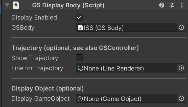
A display body may also elect to indicate that a look-ahead trajectory is to be computed. This is used when there are N-body effects and a simple orbit prediction does not show the correct future path of a body. This is a potentially CPU expensive operation, especially if there are frequent maneuvers that require trajectories to be re-calculated.
Display Enabled Flag to indicate if this body should be displayed.
GSBody The GSBody that is to be displayed with this component.
Show Trajectory If enabled the future evolution/propagation of this body will be computed by the GSController/GECore. Internally this will result in the creation of a GECore clone that runs the time ahead (by the
amount specified in the GSController) and records the future positions. These positions are then used to populate a line renderer for this display body as specified in the Line for Trajectory field.
Optional Display Object Fields
Display Object Designate a game object as the display object (sometimes the same object that has the GSDisplayBody or a child that holds the model/mesh for the body).
Rotation Display Object
Typically a game object with a GSDisplayObject has a child with some renderable mesh to represent the object in the scene. This may be a simple sphere (in the case of celestial bodies) or a mesh for a ship.
There are a number of attributes linked to a physical celestial body that can be useful in the display. If the planet radius is known, it can be used to scale the sphere mesh accordingly. If there is a rotation
axis and rate provided the information can be used to apply a rotation to the game object holding the sphere mesh. This is done if the Rotate Display Object toggle is enabled.
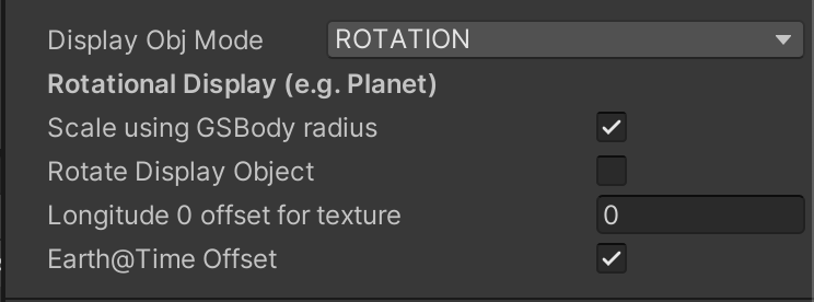
There is one toggle Earth@Time Offset that is unique to the special case of a rotating Earth. An issue arises with the initial rotation of the Earth in cases where it is important that the relative alignment of
the Earth texture correspond to a specific world time. This is described in more detail in the discussion of Earth Orbit with Map.
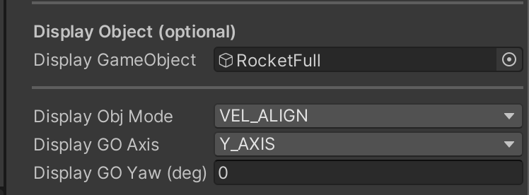
Velocity Align Display Object
The model of a display object can be aligned with the velocity of the body. This is useful when modeling a rocket launch to keep the axis of the rocket
aligned with the velocity as the rocket ascends to orbit (while pitching over as it climbs). This mode is selected by the enum value VEL_ALIGN.
When set the fields to be filled in are:
Display GO Axis: Which axis of the display object is to be aligned with the velocity vector.
Display GO Yaw (deg): How is the object to be aligned on this axis (i.e. rotation around the velocity vector)
GSDisplayOrbit#
This component displays the orbit of a body around a central mass. The plot of the orbit assumes the central mass is the only mass having a significant effect on the orbiting body and that the mass of the orbiting body is very small or zero. If the orbiting body is not nearly massless then the resulting system will in reality be rotating around the center mass of the binary pair and must be handled differently. See binaries.
An orbit may be displayed for an existing display body in the scene (if ‘Track GSDisplayBody’ is selected) or the orbit may be specified explicitly using any of the input modes that are defined for a GSBody. See gsbody.
This can be useful in cases where the scene wished to show a target orbit (e.g. geosynchronous parking orbit) without requiring a specific body to be in that orbit.
The GSDisplay that is managing the display orbit component will be called each update cycle and compute an updated orbit path and fill in the LineRenderer specified in the display orbit component. It will also update the orbit parameters in the
inspector, if this is visible in the Unity editor.
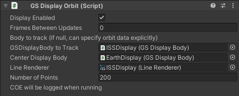
The fields in the inspector are:
Display Enabled: Check box to indicate the component should update the line renderer and inspector values.
Frames Between Updates Number of Update() frames between updates to the orbit display line renderer. Computing all the points on an orbit path
can consume significant runtime when many orbits are displayed. This parameter allows the update to be performed less often. The GSDisplay code
that manages this ensures that the orbit computation for multiple display orbits is spread out over multiple frames to avoid “bursty” updates.
Track GSDisplayBody: If enabled indicated that the orbit to be plotted is the orbit of a specified GSDisplayBody with respect to a center object
(also a GSDisplayBody). If this option is not selected the inspector will look different and will display the same style of input as appears in a GSBody to
specify the initial data for the body (RV, COE etc.)
GSDisplayBody To Track: Reference to the body to show the orbit of, If null the inspector will display the same style of input as appears in a GSBody to
specify the initial data for the body (RV, COE etc.)
Center Display Body: Reference to the object the tracked body is in orbit around.
Line Renderer: Reference to the line renderer to be used to display the orbit
Number of Points: Number of points to plot for the orbit
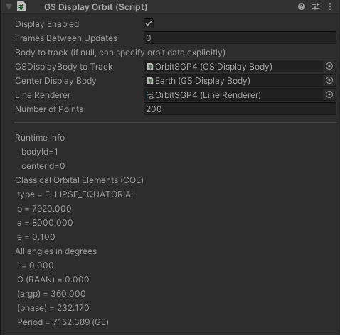
Orbit Elements in Inspector#
When the scene is running the inspector for this component will provide a live log of the orbital elements as shown below. This can be a useful way to examine orbits and debug scene setup and scripting issues.
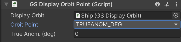
GSOrbitPoint#
A specific point in an orbit can be visualized by using the GSDisplayOrbitPoint component. This takes a reference to a GSDisplayOrbit and then provides a selection of the
standard points in an elliptical orbit. Alternately an orbit position can be specified by a the orbital angle (true anomaly) expressed in degrees.
Note that depending on the orbit shape, not all orbit locations are valid:
a circular orbit does not have an apoapsis or periapsis since all points are equidistant from the center. (a phase of 0 will be used if this applies)
ascending and descending node only apply to an inclined orbit (a phase of 0 will be used for a flat orbit)
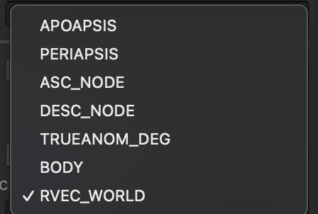
The enum for the orbit point has values:
APOAPSIS: Point farthest from the center. Not well defined for circular orbits
PERIAPSIS: Point closest to the center. Not well defined for circular orbits
ASC_NODE: Ascending node. Point where the orbit crosses the orbital plane (XY) in the direction of increasing Z. Defined for a right-handed coordinate system. Not defined for flat (\(i=0\)) orbits.
DESC_NODE: Descending node. Point where the orbit crosses the orbital plane (XY) in the direction of decreasing Z. Defined for a right-handed coordinate system. Not defined for flat (\(i=0\)) orbits.
TRUE_ANOM: True anomoly: the phase angle from the center of the orbit in a counterclockwise direction from the X-axis. (RH coordinates)
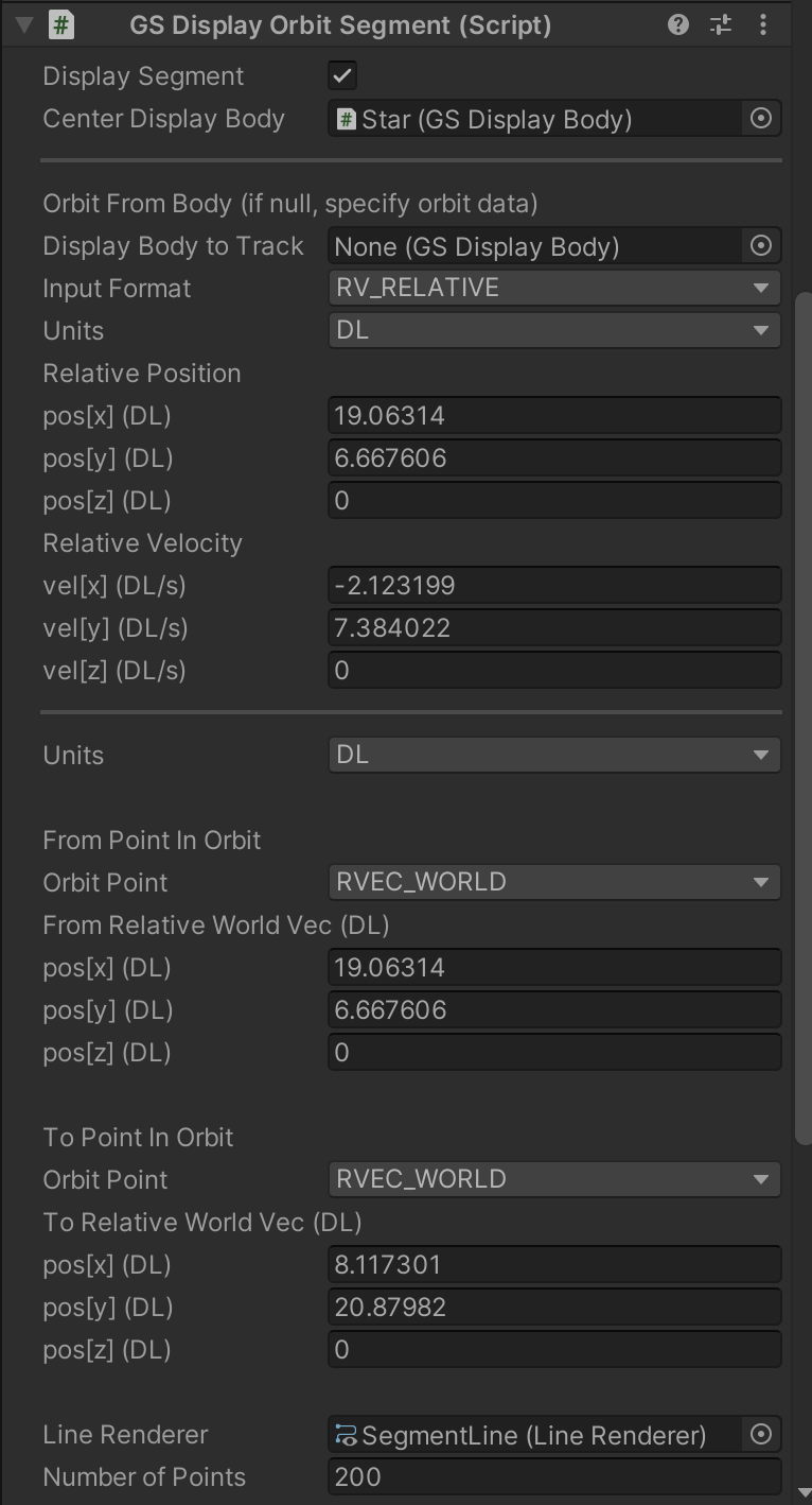
GSDisplayOrbitSegment#
An alternative to display the entire orbit of a body is to display a segment of an orbit. This is used in the multi-maneuver scene to show sections of orbits that are between orbit changes due to maneuvers. The overall component is similar to full orbit display but additional information about the from and to locations in the orbit are required. A position in an orbit can be expressed as one of several choices:
This allows the selection of the typical orbit points (apoapsis, periapsis, nodes; assuming these are valid for the orbit shape) or the position of a specific GSBody or an absolute position
vector.
The full inspector view is:
GSTransferShip#
One of the workhorse components in GE2 is GSTransferShip. It handles the “make it so” task of orbital mechanics. How does a ship in orbit A get to point B or rendezvous with a ship in orbit B?
At a high-level, the component needs to know:
the ship to maneuver
the target orbit or ship
reach orbit, rendezvous or intercept
The general operation of Lambert transfers is somewhat nuanced. A series of sample scenes are provided in the samples Tutorials_GoingFurther/9_LambertInDepth.
When the transfer is initiated (either with the key press ‘T’ if enabled, or with a call to the Transfer() method) the code will compute the maneuvers required to
accomplish the indicated end state. GSTransferShip is a scene component wrapper for the TransferShip script, a non-Mono class that does the core calculations and
in turn relies on scripts that compute Hohmann and Lambert transfers. For pure scripting applications this script can be used directly.
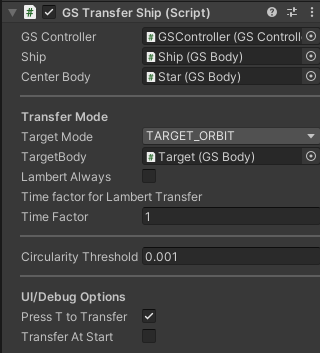
The inspector fields are:
GSController: The GSController component that has responsibility for both the ship and the center body.
Ship: A reference to the GSBody for the ship that will be maneuvering
Center Body: A reference to the GSBody that the ship is in orbit around.
Transfer Mode: A selector that determines what the target of the transfer is (e.g. orbit vs another ship). Depending on the selection
there will be input requested to denote a target ship (GSBody) or a target orbit (GSDisplayOrbit)
SHIP_TO_ORBIT: Transfer to the indicated target orbit
TARGET_ORBIT: Transfer to the same orbit as the target ship
TARGET_RDVS: Transfer to rendezvous with the target ship.
TARGET_INTERCEPT: Transfer to intercept the target (do not match target velocity with a final maneuver)
SHIP_TO_POINT: Transfer to the specified point
CIRCULARIZE: Circularize the orbit at the current position. Does not require any target information.
LAMBERT_RDVS_WITH_DELAY: Specify a Lambert rendezvous to a target ship. The transfer time and a delay before the transfer is initiated must be specified in world time units. The Lambert Always field will be set to true and may not be modified in this mode.
Lambert Always: Require the computed transfer to always be a Lambert transfer even if both the initial and final orbits are circular.
Lambert Time Mode: (RELATIVE_TO_NOMINAL or WORLD_TIME) Lambert transfer requires a transfer time to be specified. In general it can be difficult to estimate how long a transfer will take. The RELATIVE_TO_NOMINAL allows the time factor to be expressed in terms of the minimum energy Lambert transfer time. If WORLD_TIME is specified the absolute time value for the transfer will be used.
Time Factor/Time: When RELATIVE_TO_NORMAL is selected the value here is a relative multiplier. For example 0.8 indicates a transfer time of 0.8 * the minimum energy transfer time. When WORLD_TIME is selected this is the transfer time in world time units.
Retrograde Transfer Select the Lambert transfer that moves the transferring body in a direction oppposite to it’s current motion. (In almost all cases this would be impractical except if orbiting a low mass asteroid, otherwise the delta V required would be more than a ship would reasonably carry).
Check Hit vs Center Body Radius Check to see if the orbit path will interesect the body. This requires the GSBody of the center body has the radius specified in its optional physical info block. If a hit is detected a warning message will be logged. The transfer will continue.
Legacy Retrograde: In the original Gravity Engine asset the notion of retrograde was simple “the other way around” from the minimum energy transfer. In GE2 it means
the satellite direction of motion should reverse. If the older behaviour is desired, then this flag should be set.
Circularity Threshold: Defines an eccentricity threshold for the purposes of determining if an orbit is circular. Tranfers between circular orbits can use a Hohmann transfer. This is the most effecient transfer and has a well defined transfer time.
There are two UI/debug options:
Press T to Transfer: Enables checking for the press of the ‘T’ key and initiates a transfer when it is pressed.
Transfer At Start: Initiates the transfer as soon as the scene has started and GE2 has initialized.