Circular Restricted Three-Body Systems/Cis-Lunar Space
Contents
Circular Restricted Three-Body Systems/Cis-Lunar Space
The evolution of gravitational systems with three bodies can be easily accomplished with GE2 by creating a system with three bodies. The evolution of the bodies in such a system can only be determined by evolving the bodies forward in time. The paths the bodies take is in general chaotic and will not be described with a simple set of parameters in the way that classical orbital elements describe an orbit around a single body.
In special circumstances, for example a spacecraft in the Earth-Moon or Sun-Earth system, there is a clear heirarchy in the masses of the bodies. The primary body (e.g Earth) is much heavier than the secondary (e.g. Moon) and the spacecraft is massless for the purposes of force calculations. This is still a “three body problem” but the orbit of the secondary around the primary can be considered as a “typical” two body orbit. Even in this special case the motion of the spacecraft cannot be determined analytically (i.e. there is no formula). The motion must be evolved numerically.
An additional restriction is often imposed when studying these scenarios: the orbit of the secondary is made circular. This is then given the name “Circular Restricted Three Body Problem” (CR3BP).
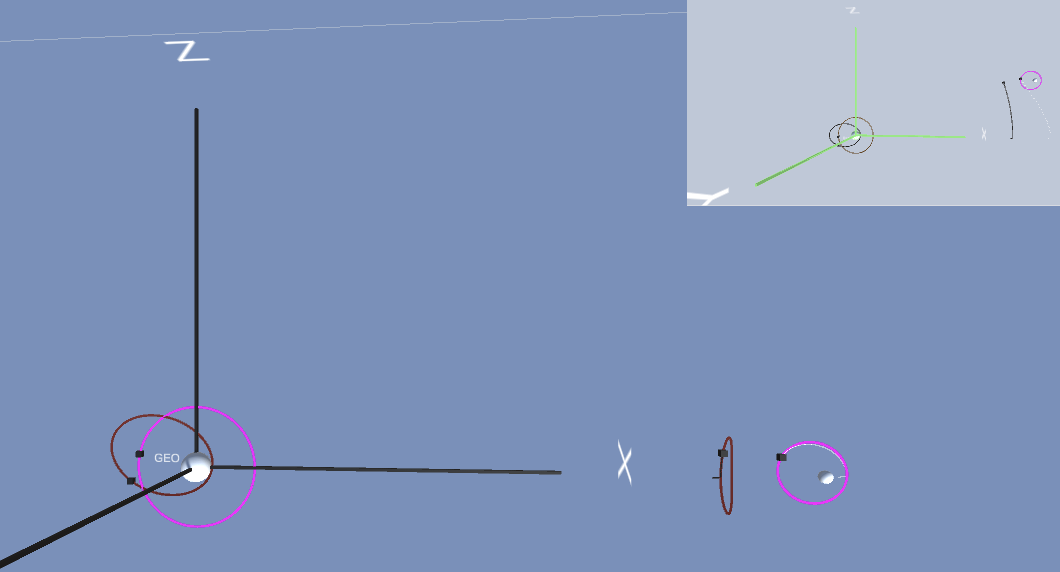
The interesting characteristics of spacecraft motion in the CR3BP are best understood by relating the spacecraft position to the positions of the primary and secondary masses. A typical view of these orbits shows the primary and secondary on a horizontal line and shows the spacecraft motion in this frame. In reality the secondary is rotating around the primary. This reference frame is one that is co-rotating with the secondary. Imagine a camera far above the Earth-Moon orbital plane looking down and spinning at the same rate as the Moon’s orbit so the Moon does not appear to move. This is named the co-rotating frame. Typically the length scale in the co-rotating frame is adjusted so that the distance between primary and secondary is 1. The origin of the co-rotating frame is the center of mass of the system (NOT the center of the primary!).
In discussions of configurations and initial conditions for halo orbits in cis-lunar space it is common to provide the specific configuration \((r, v)\) in terms of this scaled, co-rotating frame. The Jet Propulsion Lab (JPL) has an extensive collection of precomputed CR3BP special orbits Three Body Periodic Orbits. They are expressed in the co-rotating frame.
The Co-rotating frame
The co-rotating frame for the CR3BP is a frame in which:
the primary and secondary are located on the x-axis, 1 unit apart
the origin is the center of mass
an object that is co-rotating with the frame has velocity=0 (so e.g. the secondary has \(v=0\))
This is different from the inertial frame in which the secondary is rotating around the center of mass (i.e. non-zero velocity).
A CR3BP system is enabled in GE2 by:
setting the
Enabledflag in the GSController CR3BP foldout(scripting) creating a GECore using the constructor that has a
cr3bpSystemparameter in it’s signature.
The details of the setup are described further below.
A CR3BP system in GE2 will evolve bodies in the corotating frame. It does numerical integration of a modified set of physics equations that have the effects of a co-rotating frame “baked in”. These equations can be found in many astrodynamics/celestial mechanics textbooks as well as at JPL CR3BP. (My current favorite is Interplanetary Astrodynamics by Spencer and Conte).
Conversion between the co-rotating and inertial frames is provided where needed in the GE2 setup and display code. For example,
in a CR3BP system it is still possible to initialize a body in Earth or Moon orbit with a COE or relative velocity. In addition
non-Gravity propagators (e.g. Kepler) can be used for bodies in orbit around the primary or secondary. For those who wish to delve deeper
the conversion functions can be found in the CR3BP class.
CR3BP Setup
This section describes the setup of the example scene CisLunar_TwinView. This scene provides an example in which:
there is an Earth-Moon system with co-rotating physics evolution and display
there is an alternate display that shows the inertial frame (as a mini-map)
a cis-lunar orbit near L1 is initialized from JPL data
satellites are placed in orbit around the Earth and the Moon using inertial initial conditions
The scene looks like
[VIDEO]
The heirarchy of the scene is setup as:
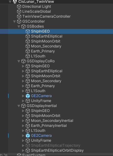
The bodies in the scene are all children of GSBodies. There are two display controllers GSDisplayCoRO and GSDisplayInertial.
Each of these has a set of children that have GSDisplayBody, GSDisplayOrbit for the evolving bodies. The body that is moving
in cis-lunar space L1South in the co-rotating view has trajectory prediction enabled in its GSDisplayBody to provide a view of the future path.
This helps visualize the halo orbit in the co-rotating view.
Controller Configuration
CR3BP is enabled in the top level GSController. This section also priovides some other important configuration details.
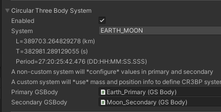
Enabled: indicated the controller should create a CR3BP GECore
System: Allows selection of one of a pre-configured set of CR3BP systems, corresponding to the systems for which JPL orbit data is available. A custom setting is also provides (see custom). The reference length and timescales for the selected system are displayed in the editor.
The next two fields behave differently in custom vs a selected system. When used in a selected system the mass of these bodies will be
configured by the GSController script to ensure that they match with the selected system. For a custom system the masses of these bodies will
define the masses of the primary and secondary.
Primary GSBody: Reference to the primary GSbody
Secondary GSBody: Reference to the secondary GSBody
Positions of the primary and secondary bodies will be configured to be on the x-axis such that the senter of mass of the pair will be at the origin.
In a CR3BP system note the following:
state information of bodies (e.g.
GECore.StateById) will by default be converted to the inertial frame in world units. The co-rotating state can be retrieved by setting the optional parametermaintainCoro.GSDisplayhas an optionMaintain CoRoto provide the typical co-rotating view (see the sceneCisLunar_TwinViewto see a picture-in-picture view of each option)
Cis-Lunar Body Configuration
In the CisLunar_TwinView scene the object L1South is a body that is initialized with data corresponding to a periodic orbit
determined by JPL. The body configuration is:
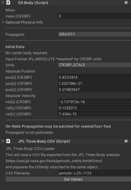
Note that:
the
GSBodyinput data hasUnitsset toCR3BP_SCALE. This forces the input mode to beRV_ABSOLUTE. The position and velocity are the co-rotating scaled values.there is a
JPLThreeBodyCSVscript. This script is used in the inspector to read values from a file saved from the JPL web site and loads them into the attachedGSBody. This occurs when theSet Valuesbutton is pressed. The CSV file from JPL has been saved in theResourcesfolder in the same directory as the sample scene.
A CSV file can be created by navigating the [JPL Web Page] (https://ssd.jpl.nasa.gov/tools/periodic_orbits.html#/intro), setting up
the orbit filter and loading orbits. Then selecting a row in the orbit table and selecting Download i.c.s will retrieve the
required file. This is the preferred way to get initial conditions for a periodic cis-lunar orbit. They are tricky things to find and
JPL has done a LOT of work to find these. Even so, many are not stable orbits. They are periodic in the sense that they stay
within a reasonable region for several cycles. Those with a higher stability index will stick around longer. There are stable orbits
around the L4 and L5 Lagrange points but most orbits of interest in cis-lunar space are near L1 or L2.
Display Configuration
The examples scene CisLunar_TwinView shows the two common display options for a CR3BP system. The most common display shows the motion
of bodies with respect to the fixed Earth-Moon system. This is done with a GSDisplay component in the usual way with one minor difference:
the Maintain CoRo toggle at the bottom of the inspector is checked.
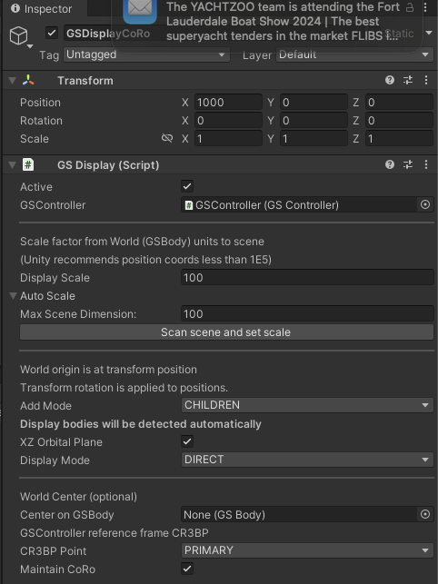
The resulting display has the x-axis of the corotating coordinate plane along the horizontal axis of the view with the origin set to the center of mass.
If the preferred center is the primary of the CR3BP system the CR3BP Point can be set to this in the GSDisplay:World Center section of the inspector.
(This also allows the selection of other standard reference points to be the display center: secondary and Lagrange points)
Note that
XZ orbit plane is selected to ensure the standard orbit orientations are shown.

In the co-rotating display bodies that are in orbit around the Earth or Moon can use GSDisplayOrbit as usual. The display code will adapt the the co-rotating coordinates.
Note that an elliptical orbit that is fixed in inertial space will appear to rotate in the co-rotating view. Orbits in cis-lunar space cannot be predicted with a Kepler orbit
predictor so their trails can be illustrated in one of two ways. The past path can be shown by attaching a Trail object. The future path can be shown by enabling the
Show Trajectory toggle in the GSDisplayBody and setting the trajectory duration in the GSController.
If the Maintain CoRo toggle is not checked then the display routine will automatically convert the internal co-rotating vales to the inertial view. This is the “usual”
view of bodies around a center body, the Moon will move in it’s orbit around the Earth, and the Earth will wobble slightly as it orbits the center of mass of the Earth-Moon
system (which is just within the Earth’s sphere). If an Earth centered view is desired this can be accomplished by setting the Center on GSBody field in the World Center portion of
the inspector fields to be the Earth GSBody. The GSDisplayInertial in the smaple scene does this.
Custom CR3BP Systems
TODO
