Orbit Transfers
Contents
Orbit Transfers
Hohmann
TBD
Lambert
The Lambert transfer is the swiss-army knife of orbital transfers. It allows a transfer from one location to another in the gravitational field of the planet. At it’s core a Lambert transfer is looking to answer the question: if a body is at position \(r_1\) what path must it follow to get to a new position \(r_2\). To rephrase this mathematically, what conic (ellipse or hyperbola) joins the two points \(r_1\) and \(r_2\) and is an orbit in the gravitational field of the central mass? In most “usual” cases there is not one specific answer but there are a family of possible solutions. See figure 1 below. (The unusual cases are ones where the path is not a typical orbit e.g. when \(r_1\), \(r_2\) are on a ray extending from the center body).
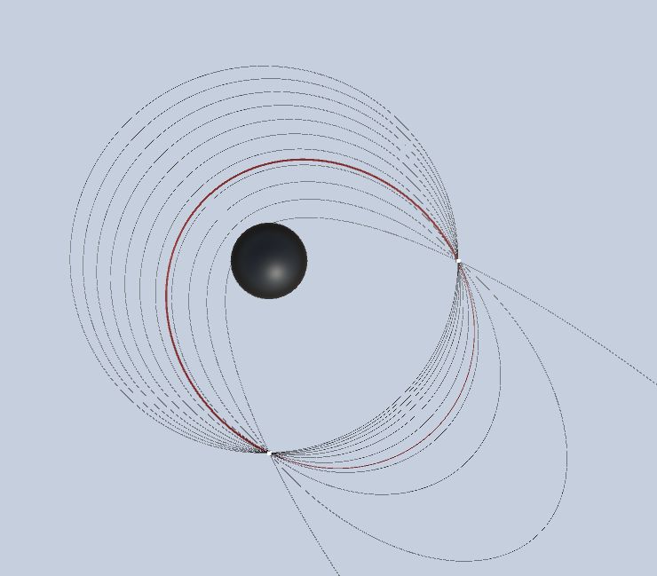
How does an orbit transfer algorithm decide on which of the possible paths to take from \(r_1\) to \(r_2\)? Additional information must be provided to constrain the path. There are several options for adding a constraint to the choice of path:
The transfer time \(t\) (This is the most common)
The path that has the lowest total energy with respect to the center
The parabolic path (\(e=1\)).
A specific angle of flight (velocity direction from \(r_1\) with respect to the local horizon).
Given one of these criteria the Lambert algorithm will find the orbital path that meets this constraint. The result will be a velocity vector at point \(r_1\) such that the orbit defined by \((r1, v1)\) will reach \(r2\). As long as the specified transit time is greater than zero there will be some conic path. As times get very short this path will approximate a straight line (with a high eccentricity hyperbola) and the required velocity can get very high (and might exceed the speed of light).
Given a time constraint there is still a degree of choice as to which conic is to be used. A ship at \(r1\) can travel along the shortest conic path with the specified time or go “the long way”. Note that these two choices result in a different conic being chosen.
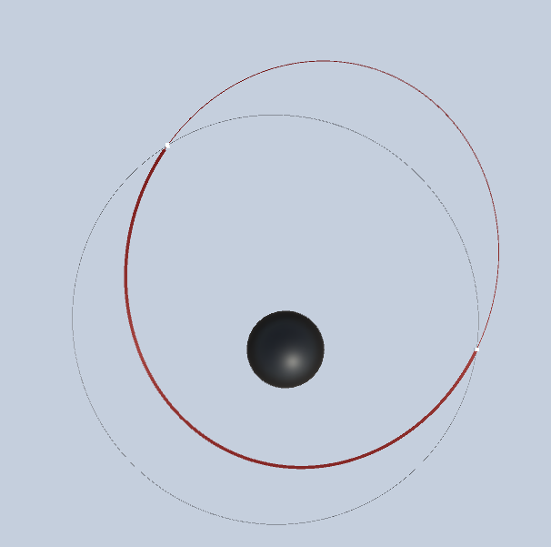
The discussion so far has made no reference to the velocity of the body at \(r_1\). When we use a Lambert transfer to plan a ship transfer we are almost always interested in a solution that minimizes the fuel required to move from \(r_1\) to \(r_2\). If we plan to rendezvous at \(r_2\) then additional fuel will be required to match velocities with a target at \(r_2\) and we may wish to minimize the total dV. In other cases e.g. a solid rocket motor there may be a specific dV required even if it is not the optimal solution. Fuel efficiency also means that for a given ship initial condition the choice of the short or long path will be based on the current direction of motion of the ship. We will generally want to avoid transfers that require the direction of orbital motion to be reversed!
The “textbook” Lambert algorithm has inputs \((r_1, r_2, \mu, t)\). It does not involve the current ship velocity \(v_1\) at \(r_1\). If we are interested in minimizing dV then we will need to iterate over various choices of \(t\) and search for a minimum dV value. If our goal is to rendezvous with an object at \(r_2\) then there is also a \(dV\) at \(r_2\) to be considered. This search over \(t\) can take several forms. If the destination point \(r_2\) is fixed then a simple sweep over the values of the Lambert constraint (e.g. time of flight of flight path angle) can be done to find a minimum dV. Unfortunately this simple case is not often useful because the point \(r_2\) denotes a target (another ship, planet) that is itself moving in time. In this case if \(r_1\) is fixed and we’re considering different transfer times the value of \(r_2\) needs to be the position of the target at the time the transfer concludes. The sample scenes with names of the form “LambertToTarget” demonstrate this.

In the most general case the optimal dV may depend on when the ship leaves it’s initial orbit. This becomes a two dimensional search, iterating over departure and arrival times. This is commonly represented as a contour or color gradient chart with departure time on the horizontal axis and arrival time on the vertical axis. Due to the characteristic shape of the contours, this is referred to as a “porkchop plot”. The sample scenes “Lambert…Porkchop” provide examples of a porkchop plot.
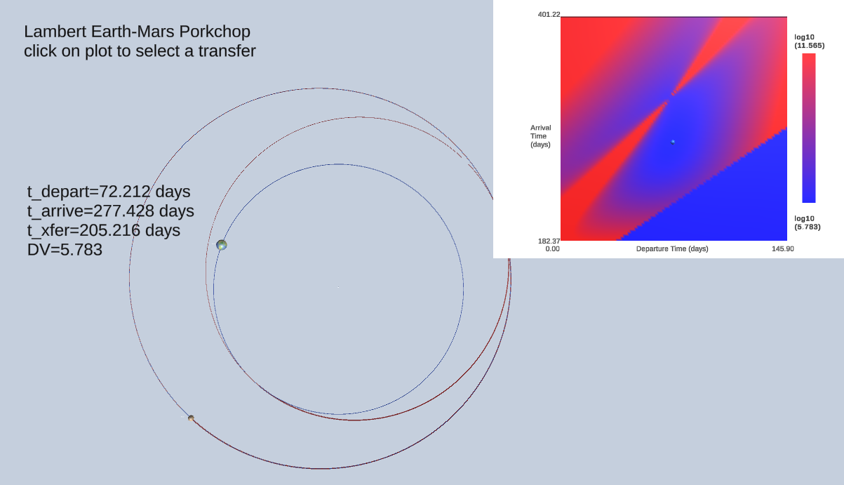
The details of these Lambert demonstration scenes is described below.
Lambert Algorithms in GE2
There is long history of algorithms to solve Lambert’s problem. The problem originated in astronomy when the question to be answered was
“given two positions and the time beteen them for an asteroid, what is its orbit?”. Famously, Gauss provided a solution for this.
(Note that Gauss had to solve the harder problem of given the positions on the sky of an asteroid and their times, what is the orbit. No one
handed him the vector positions \(r1\) and \(r2\)!). GE2 makes use of two algorithms that derive from Vallado’s book: Lambert Universal and Lambert Battin.
Why two? Lambert Universal is a good general case algorithm but it does not handle the case where \(r1\) and \(r2\) are 180 degrees apart.
The GE2 class TransferShip manages this handover internally.
Note There are currently two Lambert implementations in GE2.
TransferShipuses code from the original gravity engine. This will be deprecated in a future version in favour of the code adapted from a more recent Vallado implementation. The revised code in theLambertclass provides a simpler API and has been adapted to simplify it’s use in the Unity Job System. The description here is for theLambertclass.
The Lambert class provides a stateless API to determine Lambert transfers. The results of a transfer are returned in a LambertOuput struct that holds the input
and output details of the transfer as well as a status code. The fields in a transfer result are:
public struct LambertOutput {
    public double3 v1t; // velocity of transfer path at start of transfer
    public double3 v2t; // velocity of transfer path at end of transfer

    // record the to/from state (may not know velocities)
    public double3 r1, v1; // state at start of transfer
    public double3 r2, v2; // state at end of transfer

    public double t0;

    // time of flight
    public double t; // time of flight of the transfer
    public Status status;
    ...
They key API methods are:
TransferProgradeToPoint: transfer to a specific destination point given a transfer timeTransferProgradeToPointWithFPAtransfer to a specific point given a flight path angle (direction to travel to target)TransferProgradeToTarget: transfer to intercept a target object in the indicated time
All of the prograde methods make use of the current ship velocity to ensure the chosen transfer does not require the
ship to reverse its orbital direction. This can be disbaled by setting the optional prograde flag to false.
The mothods will also check if the resulting transfer hits the central body if the optional radius parameter is specified. A status
of HIT_PLANET will be returned if this occurs. The resulting LambertOutput will still contain a valid transfer.
Applying a computed Lambert transfer to a scene is done by adding ship maneuvers derived from the LambertOutput by using code such as:
    List<GEManeuver> maneuvers = lamOutput.Maneuvers(center.Id(), ship.propagator, intercept: false);
    gsController.GECore().ManeuverListAdd(maneuvers, ship.Id(), 0.0);
Transfer To a Point The simplest use-case for a Lambert transfer is a transfer to a specific pointin a given time. The API is:
/// <summary>
/// Solve the Lambert problem for a prograde transfer and given timeXfer to a specific fixed
/// destination point.
///
/// The default is prograde but this can be optionally over-ridden to force a retrograde transfer
/// direction.
///
/// </summary>
/// <param name="mu">gravitational parameter of central body</param>
/// <param name="r1">position vector at departure</param>
/// <param name="r2">position vector at arrival</param>
/// <param name="v1">velocity vector at departure</param>
/// <param name="timeXfer">time of flight</param>
/// <param name="radius">radius of central body</param>
/// <param name="prograde">if false, force retrograde transfer</param>
/// <returns></returns>
public static LambertOutput TransferProgradeToPoint(double mu,
                                            double3 r1,
                                            double3 r2,
                                            double3 v1,
                                            double timeXfer,
                                            double radius = 0.0,
                                            bool prograde = true)
Transfer To Target A transfer to a target object requires that the position of the target be updated as the ship moves along the transfer path. The transfer to target API performs this. The API is:
/// <summary>
/// Solve the Lambert problem for a prograde transfer and given timeXfer to a target in motion.
/// The position and velocity vectors of the target are computed at the time of arrival.
/// </summary>
/// <param name="mu">gravitational parameter of central body</param>
/// <param name="r1">position vector of interceptor at departure</param>
/// <param name="r2">position vector of target at departure</param>
/// <param name="v1">velocity vector of interceptor at departure</param>
/// <param name="v2">velocity vector of target at departure</param>
/// <param name="timeXfer">time of flight</param>
/// <param name="radius">radius of central body</param>
/// <param name="prograde">if false, force retrograde transfer</param>
/// <returns></returns>
public static LambertOutput TransferProgradeToTarget(double mu, double3 r1, double3 r2, double3 v1, double3 v2, double timeXfer,
                                            double radius = 0.0, bool prograde = true)
Lambert to Point Demos
The demo scene LambertToPointPlanner demonstrates the use of the Lambert class to examine a set of possible transfers between points. It provides a slider to
adjust either the transfer time or the flight path angle and shows the resulting transfer. In addition it runs a job to search the parameter space of times or
flight path angles and creates a plot of the departure deltaV versus the parameter. All this is done by the LambertFPAPlanner script. The inspector view of this
script and an explanation of the key inputs is provided below.
The key API call is Lambert.TransferProgradeToPoint. The times for a minimum energy and parabolic transfer are done via Lambert.MinTimes.
Once a transfer has been selected it can be executed in the scene by pressing the X key. This triggers code to use the most recent Lambert transfer
request to generate maneuvers, add then to the GECore and resume gravitational evolution.
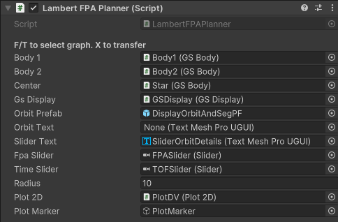
Body1 GSBody of the body to transfer from.
Body2 GSBody of a body designating the point to tranfer to to. The transfer will be to the current position of this body. (To
transfer to the resulting post-tranfser position see the Lambert to Target scene).
Center GSBody of the center body that the above bodies are orbiting.
GSDisplay the display controller for the bodies
Orbit Prefab A prefab game object that is used to display the transfer orbit.
Orbit Text Text field to fill in with details of the precomputed transfers for minimum energy and parabolic paths.
Slider Text Text for details of orbit preview based on the slider value.
FPA Slider Slider to adjust the flight path angle. Script sets default range on start to +/- FPA_RANGE_DEG (45 degrees)
Time Slider Slider to adjust time of flight. Range is set manually in the slider.
Radius Radus of the central body. If the transfer path intercepts the planet radius then the output text will add ‘hit planet’ to indicate this.
Plot2D Plot2D instance to show the DV plot
Plot Marker A game object to place on the plot corresponding to the value from the currently selected slider.
Lambert To Target Demos
The scenes with LambertToTarget in their name demonstrate how to evaluate a transfer from a ship to a moving target. In this scenario the
simple use of Lambert to determine a path from \(r1\) to \(r2\) in time \(t\) does not work because as the ship moves over time \(t\) the target
moves to a new position. To account for this, the algorithm must propagate the target to a new position based on the time requested for the
transfer. This is accomplished by the use of the Lmabert.TransferProgradeToTarget API in the Lambert class.
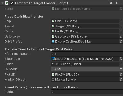
Ship The GSBody of the object to be transferred.
Target The GSBody of the object that is the target of the transfer.
Center GSBody of object that ship and target are orbiting.
GSDisplay display controller
Orbit Prefab A prefab game object that is used to display the transfer orbit.
Tranfer Time as a Factor of Target Orbit Period
The following fields all use a relative time, the fraction of the target orbit period. This allows configuration to less concerned with the absolute times in the scene since these can be difficult to estimate during setup without performing detailed calculations.
Xfer Time Factor The initial transfer time (prior to using the slider) to be shown as the transfer in the scene.
Slider Text Text for details of orbit preview based on the slider value.
Slider The slider to be used for time of transfer. Scale is releative to the target orbit period.
DV Mode Determines which deltaV calculation is to be used for the plot and reported in the text. The choices are:
DEPARTThe dV required to initiate the transferTOTALThe dV required to initiate the transfer plus the dV required to match the target upon arrival
Plot2D Plot2D instance to show the DV plot
Plot Marker A game object to place on the plot corresponding to the value from the currently selected slider.
Radius Radus of the central body. If the transfer path intercepts the planet radius then the output text will add ‘hit planet’ to indicate this.
Lambert Porkchop Demos
The most flexible search for an optimal Lambert transfer examines a range of departure times and transfer durations. The conventional way to represent this search is a plot with departure time on the horizontal axis and arrival time on the vertical axis. Some points on this plot can be excluded in advance because they represent a transfer that is either too short (dV will be too high) or too long (transfer time exceeds mission requirements). This adds an additional set of constraints to the search and reduces the number of transfer calculations required. The resulting plot they typically represents the deltaV (or some other transfer path variable) as a color coded value.
The porkchop controller will dispatch a job to evaluate a large number of transfer candidates. This will typically take a few update cycles to complete.
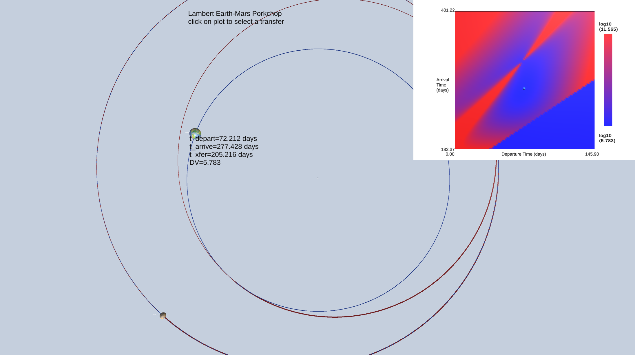
This scene is handled by the LambertToTargetPorkchop controller. It’s Inspector view is:
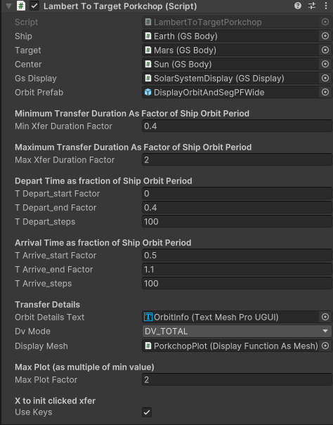
Ship The GSBody of the object to be transferred.
Target The GSBody of the object that is the target of the transfer.
Center GSBody of object that ship and target are orbiting.
GSDisplay display controller
Orbit Prefab A prefab game object that is used to display the transfer orbit.
Transfer Parameters
All the transfer times in the porkchop controller are expressed in terms of the ship orbital period.
The range of the transfer times are specified by Min Transfer Duration Factor and Max Transfer Duration Factor.
For each of the departure and arrival intervals there are inspector values for the min and max times and a field for the number of steps to be computed.
Transfer Details
Orbit Details Text Text for details of orbit preview based on the slider value.
DV Mode Determines which deltaV calculation is to be used for the plot and reported in the text. The choices are:
DEPART_VELThe magnitude of the departure velocityDEPART_DVThe dV required to initiate the transferC3_DEPARTThe C3 value for the departureDV_TOTALThe dV required to initiate the transfer plus the dV required to match the target upon arrival
Display Mesh Component to display a function as a mesh
Max Plot Factor The factor (relative to the plot minimum value) for the maximum value for the color shading. If this is too large there is limited dynamic range in the plot and it “washes out”.
Use Keys Allow the X key to initiate a transfer of the selected point in the porkchop plot.
