Rocket Launch#
Simulating the launch of a rocket from a planet surface into orbit is supported in GE2. It allows:
initial positioning of the launch site
designation of a target inclination for the desired orbit
selection of ascent control/guidance (e.g. gravity turn, PEG)
modeling of fuel consumption, throttle adjustments and staging
effects of atmospheric drag
Modelling a rocket launch creates some interesting issues for GE2. These are outlined in the implementation notes to help developers understand why the specification of a rocket launch in GE2 has so many “moving parts”.
As the above list suggests, a scene that models a rocket launch will involve some complexity. GE2 makes
every effort to balance this complexity with usability. The
core element for specifying a rocket launch in a scene is the GSBoosterMultiStage component. Several examples of it’s
use can be found in the samples folder Tutorials_RealSpace/3_RocketLaunch. Specifically:
EarthToOrbitF9demonstrates a launch into a circular orbit using PEG guidance of a “Falcon 9”-like boosterEarthToOrbitmodels a different two stage rocket to Earth orbit using PEGLunarAscentmodels the launch of a single stage lunar-module type vehicle using a gravity turn from the surface of the moon
Examples for the setup of a rocket launch using the scripting interface can be found within the GSBoosterMultistage code.
“Big Picture” Overview#
Evolution
A booster typically consists of multiple stages and GE2 provides ways to model the evolution of the booster as a collection
of GSBody objects (one per stage). This allows the independent evolution of stages after they have consumed their fuel and
been “dropped” while the rest of the stack continues its ascent. (An eventual goal is to add code to guide a discarded booster back to a landing, this is not yet implemented.)
If the goal of the scene is to only track the payload (the top stage) the
configuration can be simplified by not assigning GSBody objects to the lower stages. GSBoosterMultiStage provides input fields for the relevant details of each stage (mass, thrust etc.) and an
optional GSBody that can represent the stage. The top stage must have a GSBody to represent the position of the booster.
GSBoosterMultiStage also provides some scene UI functions:
pressing the
Xkey causes a preview of the launch ascent to be computed and displayed. This is done by creating a minimalGECorewith just the planet and the booster and using the record output feature ofGECoreto retrieve the ascent path. The computation can be CPU intensive and there is an option to do this as a background task using the Unity job system.pressing the SPACEBAR starts a launch. The bodies in the scene are given the required components (
Booster,EarthAtmosphereRenetry) and the launch starts by evolving the bodies in the primaryGSControllerandGECore.events (staging, cutoff, stage collision with the planet) are handled by
GSBoosterMultiStageand callbacks are made to anyGSStageDisplayManagerelements that have registered to receive them.
GE2 will update the position of each stage and will allow the stage to evolve independently after staging has occurred. Consider a three stage
stack such as in the EarthToOrbitF9 scene. It has three GSBody objects as arguments to the GSBoosterMultiStage. When the scene starts
each body has a PLANET_SURFACE propagator. Only the top stage is actively displayed prior to launch (display details are below). Once launched
the top stage is assigned the Booster self-integrating external acceleration and the propagator is changed from PLANET_SURFACE
to GRAVITY. Each of the stages below the top are assigned an EarthAtmosphereReentry self-integrating force.
As the Booster component is called from within the GEPhysicsCore to propagate the body for the top of the stage there is logic in place
to update the positions of the bodies for those stages in the stack still attached. This is done by communication from the Booster component
to each of the EarthAtmosphereReentry components on the lower stages. Once a stage is detached it is left to update it’s own evolution and will
evolve independently of the booster.
The Booster component will handle the evolution of the launch vehicle until the fuel is exhausted or (in the case of PEG) is cutoff. At this
point the body return to standard evolution in GECore and an EXTERNAL_ACCELERATION_REMOVED event is generated.
Dropped stages will evolve using the EarthAtmosphereReentry component. This component computes the force of gravity and the atmospheric drag.
It also checks to determine if the stage has reached the surface of the planet. If so, it deactivates the evolution of the body and generates
a physics event. See physics events for a summary.
Display
The display of the booster stack is handled with a dedicated component GSStageDisplayManager. While each stage can have a GSBody and
one or more GSDisplayBody components during ascent there can be precision issues if each stage is rendered independently while they are part
of the same stack. Prior to stage separation it is
better to have a single model showing the “stack” of connected stages and only display the individual stages once they have separated.
GSStageDisplayManager handles this. This requires that it has knowledge of the booster state and that it is notified when a staging
event happens to allow it to change the model for the stack to one that excludes the just completed stage and starts displaying the
“dropped” stage with its own GSDisplayObject.
Launch Trajectory Display
The display of the ascent trajectory as a 2D altitude vs downrange distance is very helpful for assessing a launch path. The
GSLaunchDisplay provides this by acting as a custom display manager. It also has interaction with the GSBoosterMultistage to allow
the preview of launch paths to be displayed. Determining the exact guidance parameters for a launch can be tricky and require some iteration.
Scene Setup#
In the launch sample scenes the physical body and display objects are separated. In the
EarthToOrbitF9 the hierarchy is:
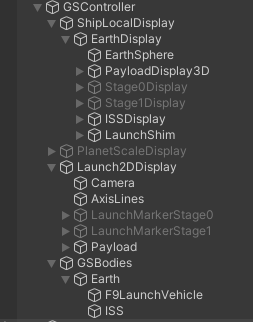
There are three main branches:
ShipLocalDisplay: A local “ship view” camera that follows the vehicle during launch
Launch2DDisplay: A 2D vertical vs horizontal plot of the ascent trajectory
GSBodies: The physical bodies added to the controller
Each of the display scenes makes reference to bodies in the GSBodies part of the tree.
GSBodies:
The bodies in the scene are in this branch of the component tree. There is a GSBody for the Earth
and it has children that represent the launch vehicle (with a body for each stage) and a body
already in orbit, ISS. The F9 game object holds the GSBoosterMultistage scene component. The
game objects StageOne, StageTwo and Payload have GSBody components and represent the bodies
that will be evolved as the vehicle launches. Initially all three are configured to have the same location
on the planet surface.
ShipLocalDisplay:
This sub-tree handles the 3D follow-along view of the launch vehicle. It has a standard GSDisplay
component and display components for each of the stages. Initially only the component for the payload
body is enabled and display objects for stage one and two are inactive. Additionally the payload display
body has three mesh models for the booster. At first the model showing the full stack is used. As staging
events occur the GSStageDisplayManager will change the model used for the payload and enable display of
each stage as it dropped.
Launch2DDisplay:
The right-hand view in the scene is a 2D launch ascent trajectory path. This is managed by a class that
extends the usual display manager: GSLaunchDisplay. This adapts the 3D positions of the boosters and
stages into a 2D altitude-downrange plot. In addition it manages the display of axis lines for reference.
This sub-tree also makes use of a GSStageDisplayManager. In this simple representation there is only a
single display model for the payload.
In preview mode a LineRenderer is used to show the ascent trajectory. During a launch the path is shown
with a trail renderer.
Initial Setup#
A rocket launch begins with an object on the surface of a planet. The rocket is represented by a GSBody
component that is configured with a FIXED propagator and initial data provided by LATLONG_POS.
The fixed propagator ensures that the object does not move (otherwise gravity would pull it through the
surface of the planet to the interior). The LATLOG_POS input requires that the center body have the
optional physical information initialized because it needs the radius of the planet to determine the
initial position.
Note
A future release will allow the fixed surface location to be placed on a rotating planet. This will also include the rotational velocity in the launch initial conditions.
The launch site will be at the correct radius from the planet center but this may not correspond
to a point on the sphere used to display the planet. The sphere renderer ensures that the vertices
of the triangulated sphere are the radius of the sphere but if the launch site location is over one
of the faces it will “hover above” the surface. The game design may choose to solve this in various ways
(e.g. rotate the model so a vertex is at the launch site). In the demo scenes the solution chosen it to
position a “shim”. A cube is positioned so that it’s top face is at the launch site and the normal is
aligned radially. See the LaunchShim component in the ShipLocalDisplay sub-tree.
GSMultiStageBooster#
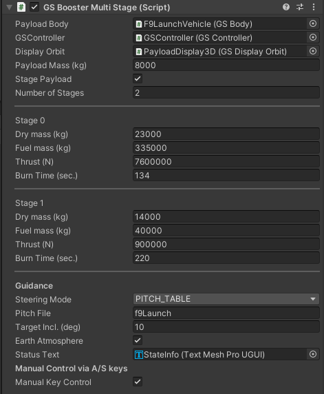
In the example scene EarthToOrbitF9 a three stage rocket is configured using GSMultiStageBooster. The
inspector for this is shown below. It seems like a LOT, so let’s take it a section at a time:
Preamble
The first section is:
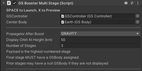
GSController: The controller for the evolution of the booster.
Center Body: The GSBody that represents the center body. This must have it’s optional physical info filled in
to ensure the radius of the planet is known.
Propagator After Boost: The orbit propagator (e.g. GRAVITY, KEPLER etc) that is to be used when the top stage
is done with booster evolution. (Initially the body is likely configured to use a PLANET_SURFACE propagator and
during launch it must use GRAVITY to allow an external acceleration).
Display Orbit at Height: TODO
Number of Stage: The number of stages in the booster. (The payload counts as a stage).
Per-Stage Details:
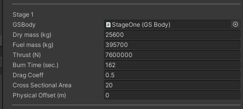
This section describes the physical parameters for the stage. Optionally it can provide a GSBody to be used to track the
body. The highest numbered stage must have a GSBody configured.
GSBody: The GSBody used to represent the stage. Optional except for the highest numbered stage.
Dry Mass (kg): The empty (dry) mass of the stage.
Fuel Mass (kg): The mass of the fuel in the stage.
Thrust (N): Thrust in Newtons.
Burn Time (sec.): Time to burn all the fuel.
Drag Coeff: The drag coefficient for atmospheric drag calculations. Typical values range from 0.5 to 2.0. In general this should be a function of speed, but for now a single number is used. Set to zero to ignore atmospheric effects.
Cross Sectional Area: Cross sectional area in square meters. Used when determining atmospheric drag.
Physical Offset (m): Distance (m) of this stage from the top stage. This is used when a stage positions are calculated as the booster ascends with stages attached.
Guidance
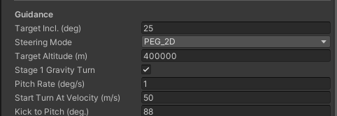
Target Incl.: Target inclination of the orbit in degrees. Note that depending on the launch latitude not all inclinations are available. The target inclination may not be smaller than the launch latitude.
Steering Mode: (depending on the steering mode the parameters in the editor view may differ)
MANUALManualmode has no parameters. The ascent is initially vertical and is changed by user input via theAandSkeys.
LINEAR_TANParam A:Param B:
PITCH_TABLEPitch Filea reference to text file in aResourcesfolder (no.txtextension)
PEG_2DTarget Altitude (m): The target altitude for the desired circular orbitStage 1 Gravity Turn: Flag to indicate stage 1 should use a gravity turn guidance modePitch Rate (deg/s): Rate used to slew to the pitch kick indicatedStart Turn At Velocity (m/sspeed to attain before gravity turn startsKick to Pitch (deg.)the angle to pitch over to to start the gravity turn (90 is vertical)
GRAVITY_TURNPitch Rate (deg/s): Rate used to slew to the pitch kick indicatedStart Turn At Velocity (m/sspeed to attain before gravity turn startsKick to Pitch (deg.)the angle to pitch over to to start the gravity turn (90 is vertical)
See guidance algorithms for an explanation of how the steering modes work.
Post-Amble
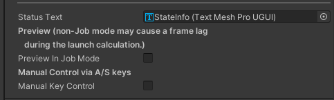
Status Text: An optional reference to a Text UI component to display status information as the launch proceeds.
Preview in Job Mode: Use Job mode for launch preview. The preview runs a GECore to fully compute the ascent
path for the preview display. This can be CPU intensive and may be best done on a background thread and displayed
once that is completed.
Manual Key Control: Allow the A and S keys to be used for manual pitch guidance during ascent.
Guidance Algorithms#
Launching a rocket into orbit from the surface of a planet requires the vehicle both move away from the surface of the planet and attain significant horizontal speed to reach an orbit that does not intersect the planet. For example, a circular orbit around the Earth at a height of 400 km requires a velocity of more than 31 km/sec. Launching from Earth the most fuel efficient approach is to “go mostly up” at first, to clear the dense part of the atmosphere and then “go sideways” to reach the required orbital speed. Balancing these to achieve the right orbit is tricky. If there is no atmosphere then the best approach allows for heading sideways earlier in the ascent.
GE2 provides several algorithms for the launch profile. A launch algorithm generally provides the pitch (angle from local vertical) as a function of the ascent time. The algorithms are described below.
Manual: This allows the user to directly control the pitch interactively.
Linear Tangent Steering: One pitch algorithm that can be used is linear tangent steering. The steering law is
derived from the equations for time optimal launch of a rocket into a circular orbit (neglecting air resistance)
using a “flat Earth” model for gravity. The steering law seems simple at first glance: it provides a function for
the angle of the booster from horizontal as a function of time.
$\(
\tan(\theta) = a*t +b
\)\(
However in practice it is unlikely values for \)a\( and \)b$ to achieve a specific orbit can be “guessed”. The specific values in the LunarAscent
scene come from the analysis at SSTO Lunar Ascent.
They are the final values of a process of searching for the optimal values for given launch and vehicle constraints.
(I hope to provide a simpler Python tool to allow users to compute values for specific scenarios).
Linear tangent steering is termed an “open-loop” guidance law. It does not measure the current position and velocity and use them in determining the pitch during ascent. The pitch profile is wired in from the start.
Powered Explicit Guidance (PEG) PEG is a closed-loop approach that does make use of the current vehicle state and determines what pitch input is best to achieve the desired final orbital state. It was used by the space shuttle and in the Apollo program (refs). PEG models the ascent of the rocket based on the current state and determines how it matches the desired state. It then adjusts the pitch to move the expected state closer to the desired state. The modelling in PEG ignores the effects of the atmosphere so it is generally used of the second stage of a two stage booster, taking over from a gravity turn ascent of the first stage.
The current PEG logic assumes a two-stage rocket and a 2-D ascent profile to a circular orbit. This will be extended in a subsequent release to allow 3D steering of an arbitrary rocket into a designated orbit that is not necessarily circular.
The Booster PEG implementation is based on the 2D code in PEG.
Descriptions of PEG generally rely on some background in control theory. Some of the references I have found useful are:
Orbiter Wiki
Thesis
PEGAS Github
Pitch Table
External code may be used to determine an optimal ascent path. In the LunarAscent demo the
pitch file lunar100km_pitch provides a pitch vs time table computed by an off-line Python script to determine
the optimal ascent to a 100 km circular orbit in lunar gravity. The guidance system consults this table and
controls the booster pitch accordingly.
Launch#
The GSMultiStageBooster acts a controller for the launch operation. When space is pressed it will launch the body.
Recall that the body was initially configured as fixed. In order to be influenced by gravity and the external acceleration
of the rocket engine the body must be changed to a GRAVITY propagator. The control code does this by deleting the
launch body and the re-adding as an object with a gravity propagator. The control code also adds a BOOSTER external
acceleration configured with the number of stages and stage specifics specified in the inspector. The booster
external acceleration also manages the ascent guidance. If the Earth Atmosphere flag is enabled the controller
also adds an Earth atmosphere model.
Staging#
Rocket staging happens automatically when all the fuel of the active stage is consumed and there is another stage in the
stack to be activated. The logic for this is part of the implementation of the BOOSTER external acceleration. This is
necessary because the physics evolution must continue through the staging time without stopping. The GECore generated
physics events to report on staging events and the GSBoosterMultiStage handles these events.
A staging event requires two actions be taken:
a new body must be created in the
GECoreto represent the spent stagedisplay code needs to show the new vehicle configuration and display the spent stage in all
GSDisplayelements that are showing the rocket
Display Logic for Ascent#
GSStageDisplayManager handles display components for a rocket launch. It takes action on launch and when a staging event is reported.
On a launch the manager ensures that any TrailRenderer components on the payload display object are set to emit a trail.
The inspector for this is:
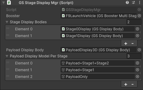
Booster A reference to the GDBoosterMultistage controlling the rocket launch.
Stage Display Bodies A list of display bodies (initially inactive) that are to be used to represent stages once they have been dropped.
Payload Display Body The payload display body. This is active by default and generally has a series of models as children. Initially the model represents the payload and all booster stages. As stages are dropped the stage manager will inactivate this model and activate the model corresponding the active stage of the booster.
Payload Display Model per Stage The model for each active stage of the payload.
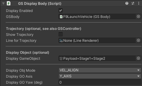
In order to align the payload and stage models with the current ascent pitch the GSDisplay components should have their
GSDisplayBody configured with a display object and display object mode set to VEL_ALIGN. For example:
Booster Implementation Notes#
GSBoosterMultistage handles the adding of the appropriate components to GECore based on the configuration provided. In the case
where each stage has a GSBody component each will be configured.
Booster evolution is handled by a self-integrating external acceleration that overrides the normal GE2 physics evolution. This is
by necessity because the time scale for a typical booster ascent is very short compared to the time scale for a satellite orbit.
The booster evolution requires timesteps on the order of one second or less. Using this as a global timestep would result in
significant CPU work for all satellites and other gravitational bodies in the scene. Hence the need for a dedicated self-integrating
external acceleration with a dedicated short timestep. This is handled by the Booster class.
The Booster class models:
rocket thrust
fuel consumption
staging
Earth atmospheric drag (based on
Atmosphereclass)guidance
By default an Earth atmosphere model is used. To avoid drag the drag coefficient of each stage must be set to zero.
The re-entry of a spacecraft or booster stage also requires a self-integrating propagator. Like the boost phase, the final re-entry
of an object happens on a timescale of minutes. The class EarthAtmosphereReentry implements this function.