Tutorial: Ship Multiple Maneuvers#
In the Tutorials_GoingFurther directory there is a “mini-game” that provides a framework for creating a sequence of
manual maneuvers, illustrating the consequence of each maneuver as the future trajectory is put together. This
provides a concrete example of how to create maneuvers, make use of display objects to show the
sections of motion and how to find points of interest (apogee, perigee, nodes) in an orbit.
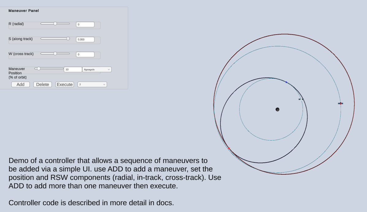
The goal of the scene is to allow a player to plan a sequence of maneuvers for a ship in orbit around a single body. The scene will begin with a ship in orbit around a planet with the current orbit shown. A simple Unity canvas UI will be used to allow the player to indicate where/when a maneuver is to be added.
Once a maneuver has been added the scene enters “maneuver planning mode”. GE2 evolution is stopped. The player can then indicate where the maneuver is to happen as a percentage of position around the orbit or by selecting a “point of interest” (apogee, node, periapsis or apoapsis).
The player will manually design the maneuver by adjusting the change in velocity at the maneuver point using sliders to adjust each of the three velocity components. The velocity changes are made relative to the current ship position using a standard coordinate system referred to as RSW [REF]. By convention these directions are:
R (radial) component towards the planet being orbited
S (in track) normal to R and W
W (out of plane) along the direction of the orbit axis
Note that the S direction is determined by the cross product of R and W and is not necessarily in the direction of the ship velocity unless the ship is in a circular orbit. The vector orientation is in the direction the ship is orbiting.
A screen shot of this scene is provided below. There is also a tutorial video.
This process can then be repeated, adding further maneuvers in sequence.
Once the path has been designed the player can click an EXECUTE button to resume GE2 evolution. The controller will then add a sequence of maneuvers to accomplish the trajectory specified and manage the removal of the planning segments as the maneuvers progress. Alternately, the path can be made reversible if the scene is all on rail and the ship is set to KEPELR mode with patches enabled. This is described further below.
Solution Architecture#
The core GE2 components GSController and GSDisplay together with a ship and planet (GSBody, GSDisplayBody for each) and a GSDisplayOrbit to show the ship’s orbit
are the basic starting point for this scene. This gives us a foundation of a ship orbiting a planet.
A custom controller, ManeuverController for the scene will be needed. This will:
provide an API to add maneuver points, change their positions and relative velocities
in response to an Add it will instantiate a maneuver point object (from a prefab) and then position the maneuver point on the ship’s current orbit
the maneuver point will hold a
GSDisplayOrbitthat is configured directly with an R and V for the point in the orbit, plus any velocity changes from the UI slidersthe maneuver point also holds a
GSDisplayOrbitSegmentthat allows intermediate maneuvers to display a portion of the path between maneuver pointsadditional maneuver points can be added at points on the orbit defined by the preceeding maneuver
once the series of maneuver points has been added these can then be “executed” by converting each maneuver point into a GE maneuver and adding these to the GECore.
The controller will need to interact directly with the GE2 classes to get information about the ship orbit and to determine the appropriate world positions and velocities for points in each of the orbits for maneuver points. The key touch points with the GE2 API are described in the implementation section below.
The UI components of the scene will be handled by a separate ManuverControllerCanvas class.
This handles the mapping of UI events (buttons presses, slider changes) into the API calls
to the ManeuverController. This is a fairly straight-forward class and the implementation can be
examined for the details.
Implementation Details#
The ManeuverController defines an internal class to mark a maneuver called Marker. It encapsulates:
a display orbit instance
the state of the orbit at the marker point (r, v) and the time this point is reached
the deltaV (dV) that will be applied (in the RSW frame)
the unit vectors for the RSW frame (these depend on the maneuver position, r)
The controller maintains a list of markers and these represent the sequence of maneuvers that will be applied. Each marker is referenced to the orbit of the preceding marker. The first marker is referenced to the position of the ship’s orbit.
The key elements of the ManeuverController API are:
ManeuverPointAdd: Create a marker, instantiate the prefab and setup the associated orbitPositionSet: Update the position of the currently active marker and it’s orbitDvSet: Update the velocity of the marker and it’s orbit
Let’s walk through these by outlining how the first maneuver point is added, when the UI code calls
into ManeuverPointAdd (the UI also calls the SetPaused method to stop GSController evolution of the scene)
the prefab for a maneuver point is instantiated
since there are no preceeding markers the ship marker is taken as the preceding marker
the (r, v) for the marker is computed by copying values from the preceding marker
the marker setup code is run to determine the axes of the RSW coordinates
the
GSDisplayOrbiton the prefab is set to have the planet as the center and the maneuver point with the current (r, v) as its initial statethe
GSDisplayOrbitSegmentis set inactive since this is not (yet) an intermediate maneuverthe marker is added to the list of active markers
The API call for a ManueverAdd is:
   /// <summary>
   /// Add a maneuver point to the scene.
   ///
   /// This is initially located at the same point as the last maneuver but then is
   /// usually immediately modified by a PositionSet() call.
   ///
   /// </summary>
   public void ManeuverPointAdd()
At this point we have a marker object created at exactly the ship position. Since this is “on top of” the ship
position, the UI then calls the PositionSet method to move the maneuver marker along the orbit a small amount.
We’ll look at that API next.
The API call is:
   /// <summary>
   ///
   /// Set the indicated marker index. A variety of units and positioning schemes are supported:
   /// In all cases the position is from the ship or from the proceeding marker if there are > 1 markers.
   /// PERIOD_PERCENT: Place some percent of orbital period ahead
   /// TIME_AHEAD: Place at a given physics time ahead
   ///
   /// The following choices allow for placement at an orbit point:
   /// APOAPSIS, PERIAPSIS, ASC_NODE, DESC_NODE, ALT_FOR_RADIUS_1, ALT_FOR_RADIUS_2
   ///
   /// Changing the position of the marker will not reset the dV in the marker. That must be done
   /// explicitly.
   /// </summary>
   /// <param name="pMode">Position mode</param>
   /// <param name="value">Percent period (0..100) or time depending on mode</param>
   /// <param name="index">Index of maneuver to apply to (active if default)</param>
   public void PositionSet(PositionMode pMode, double value, int index = -1)
The implementation of this method begins by finding a description of the orbit on which a position is being set. In the case of the first maneuver this will be the ship’s orbit and the orbit information is retrieved from the ship marker via:
Orbital.COE fromCOE = fromMarker.orbit.LastCOE();
Orbital.COE is a struct that holds the classical orbit elements of the ship.
Depending on the PositionMode indicated in the API call the next step will differ. Those modes
that correspond to a specific point in the orbit e.g. apoapsis there is a utility function that
will determine the position based on the point in the orbit. This code is:
    Orbital.OrbitPoint orbitPoint = (Orbital.OrbitPoint)(pMode - PositionMode.APOAPSIS);
    (r, v) = Orbital.RVForOrbitPoint(fromCOE, orbitPoint);
There is a bit of sneaky enum conversion here, relying on the fact that the orbit point enum and position mode enum encode orbit points in the same order.
If the position is specified by a time or percent offset, then a different orbit API call is used. In the case of percent period the code is:
    time = fromCOE.GetPeriod() * value;
    (r, v) = Orbital.COEtoRVatTime(fromCOE, time);
Once the r and v have been determined, this provides a location for the marker point. One slightly subtle point
is that the position r is a world space position. It needs to be mapped into the scene by the GSDisplay component
to ensure it scaled and positioned appropriately. This is done by the line:
   orbitMarkers[index].orbit.gameObject.transform.position =
       gsDisplay.MapToScene(GravityMath.Double3ToVector3(r));
The key point is the use of gsDisplay.MapToScene(). The rest is just format conversion (double3 to Vector3) and
a slightly awkward way to get at the transform of the marker game object.
The other task the position set needs to do is to adjust the velocity at the new position and update the component
that is displaying the orbit. The velocity change is preserved in the dV element of the Marker internal class. This is
expressed in the RSW coordinates. The net velocity is the new velocity, v, from the position update plus this dV.
This is updated via the use of the same DvSet() that the UI uses. The key lines there are
    double3 v_new = marker.v + marker.v_mag *
                    (dV.x * marker.r_unit
                    + dV.y * marker.s_unit
                    + dV.z * marker.w_unit);

    orbitMarkers[index].orbit.RVRelativeSet(r, v_new);
marker.v_mag holds the magnitude of the velocity of the current position. This allows the dV value to be expressed as
a fraction of the current velocity. This is a useful approach to avoid issues with finding a suitable scale for the UI elements.
This way they don’t care if this is an low orbit around Earth with a high velocity or a slow orbit around an asteroid.
The execution of maneuvers is handled by a call to ExecuteManeuvers(bool removeMarkers). Adding maneuvers will require
changes in the internal state of the GECore so this is done by asking GECore to call back to the add maneuver routine
when physics processing is done. In this specific case GECore is paused and the callback will happen immediately. The
adding of maneuvers is done by AddManeuvers which is called from GECore.
The key code here is:
   for (int i = 0; i < orbitMarkers.Count; i++) {
       GEManeuver m = new GEManeuver
       {
           info = ManeuverInfo.USER,
           type = ManeuverType.SET_VELOCITY,
           velocityParam = orbitMarkers[i].v_new,
           v_relative = orbitMarkers[i].v_new,
           r_relative = orbitMarkers[i].r,
           t_relative = orbitMarkers[i].t,
           centerId = centerId,
           doneCallback = ManeuverCallback,
           hasRelativeRV = true,
           opaqueData = null
       };
       // as maneuver completed, remove previous marker
       if (i == 0) {
           m.opaqueData = shipMarker;
       } else {
           m.opaqueData = orbitMarkers[i-1];
       }
       ge.ManeuverAdd(shipId, m, t_offset);
       Debug.LogFormat("Adding maneuver: {0}", m.LogString());
   }
The code creates GEManeuver objects for each of the maneuvers and adds them to GECore. The type of maneuver used in this case is SET_VELOCITY. This
must then provide the velocity vector to be used at the time the maneuver is executed. This choice of using the relative r and v allows the use of
patch mode (more below).
The maneuvers also provide a callback and a reference to the maneuver marker. The GECore will do a callback after the physics evolution has applied the maneuver. This allows the controller code to remove the markers as the trajectory evolves and allows the player to see the remaining planned path as the ship moves.
Patch Mode and Time Slider#
The multiple maneuver scene has an optional Slider on the Canvas component. This has a TimeSlider script attached. This script is also used in the
KeplerPlanetAndMoon scene. To make use of this in the multiple maneuver scene a few minor changes need to be added to the scene:
ensure all bodies are on-rails (set Star to FIXED and both GSBodies to KEPLER)
If run like this the final path of the objects can be rewound with the time slider BUT only to the point of the last maneuver. This is because in KEPLER mode
the evolution time cannot be earlier than time when the Kepler state was defined; this is the time of the last maneuver. The is a way around this and that is
to use patch mode. Enabling patch mode on a GSBody (by toggling the Patched toggle after selecting KEPLER mode) will allow time reversal back through the maneuvers.
This works due to logic in the GECore.ManeuverAdd code. If a maneuver is being added and the body is patched and uses an on-rail propagator then instead of adding
a maneuver to the physics core at a future time, the code creates a new patch for the body. The physics core can extend an on-rails propagator to a list of
segments that are valid for specific time intervals. In the case of the first maneuver, there will be the initial orbit of the ship up until the time of the maneuver
and then a new Kepler segment to describe the orbit after the time of the maneuver. When the time slider is used the physics code will handle the transitions
between the patched.
Recall that in the non-patched case there were callbacks associated with each maneuver to handle the removal of the markers for each segment. In the patched
case these will not be invoked so a different approach is required. This is done by adding a listener to the GECore to get notifications on physics events.
A patch change causes a physics event with type PATCH_CHANGE and the code in PhysEventListener in the controller handles the removal of markers.