Tutorials: Real-World Scenarios#
Space games that require a “real-world” modelling of orbital mechanics can be created with GE2. In this section we present several tutorial examples.
The first shows satellites in Earth orbit with accurate modelling of the Earth rotation as a function of time and the tracks of satellites in 3D and projected on a 2D map.
The second tutorial shows how to use the Solar System Builder. This editor tool allows the creation of a scene with accurate data for:
planets
any desired satellites (aka moons) of the planets
any solar system small bodies (comets/asteroids)
The initial data for these bodies is retrieved from the JPL Horizons database via a web API. The solar system
creates unique scaling and physics evolution challenges which we discuss. The resulting implementation uses
a hierarchy of GSController and GECore instances to solve these challenges.
Earth Orbit With Map#
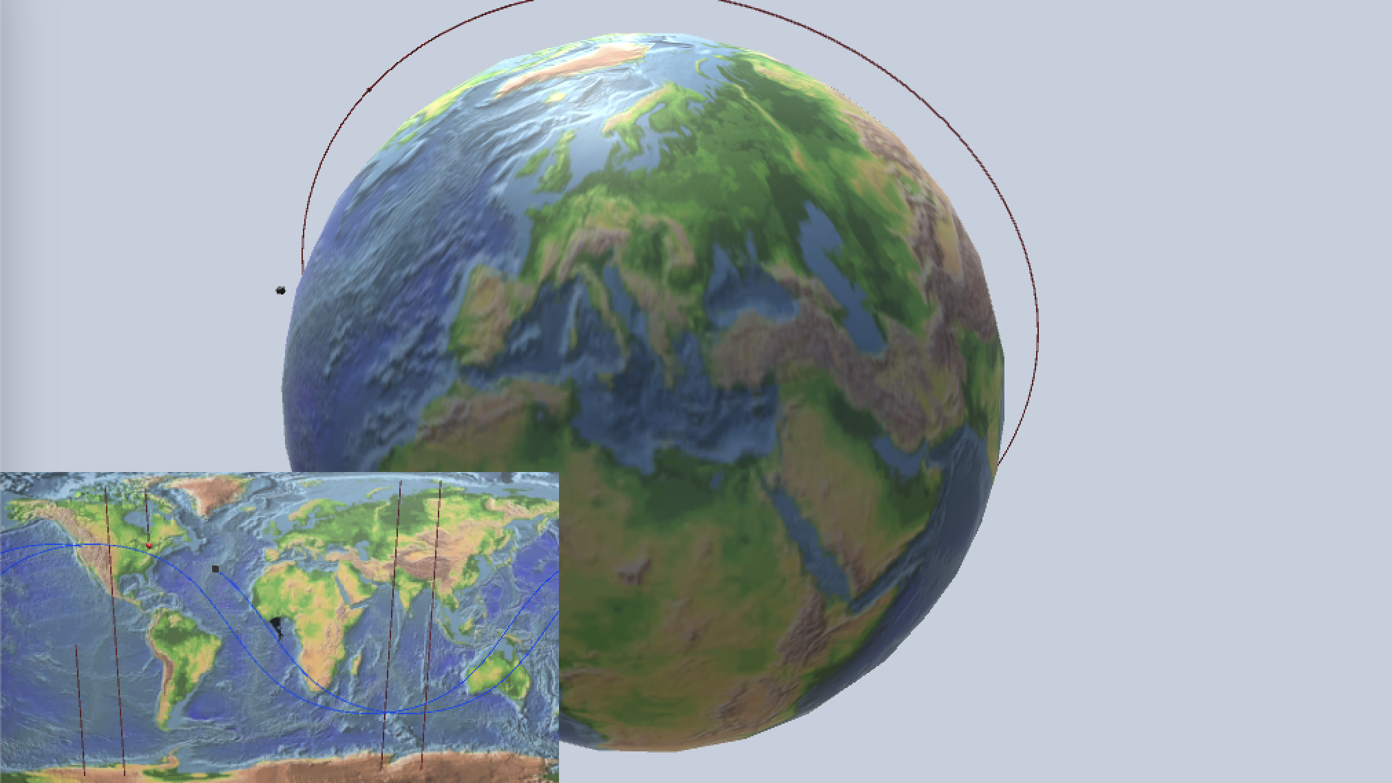
The goal for this scene is to model the orbit of satellites around the Earth and accurately show the position of the satellite over the Earth’s surface.
The sample scene presents two views of this scenario
A 3D view of the rotating Earth with satellites
A 2D map view of the Earth with satellite future trajectories shown
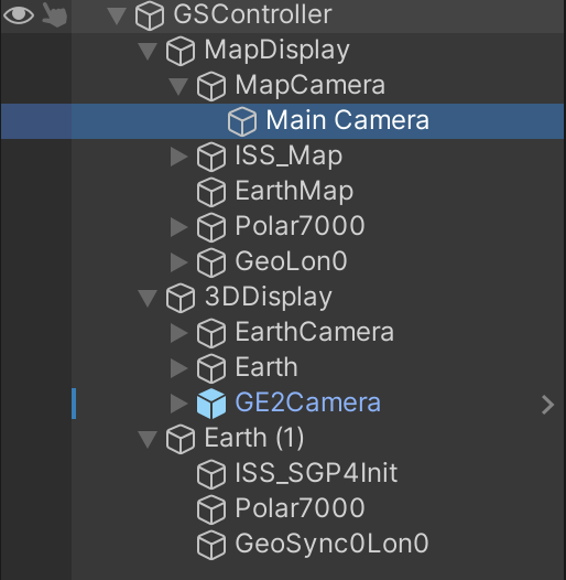
Both of these display hierarchies make reference to the same bodies. As a result the GSBody components are
children of the GSController but are not under the GSDisplay components. There are GSDisplayBody objects in
each of the display hierarchies that make reference to the GSBody components.
The scale for the scene is SI_km.
3D View#
To begin with we will need a sphere to represent the Earth and a texture that shows the Earth’s surface. Fortunately NASA provides a set of textures without usage restrictions. We make use of an Earth texture from this site in our scene.
The majority of satellite data (e.g. Celestrak) uses a standard reference frame in which the z-axis is aligned with the north pole and the x-axis is in the direction of the vernal equinox (true equator, mean equinox, or TEME coordinates). See the Celestrak FAQ and Wikipedia. The vernal equinox represents a specific direction from the solar system independent of the rotation of the Earth or the Earth’s position in orbit around the sun.
Now that we have this reference point, we’ll need the Earth in the scene to do two things:
be in the correct orientation wrt the x-axis for the start date and time given
to rotate at the correct rate
Rotating the Earth:
The rotation parameters of a GSBody can be specified in the Optional Physical Info dropdown in the inspector.
This is where we specify the rotation axis in physics space as the z-axis, and the rotation rate in radian/sec.
These are \((0, 0, 1)\) and \(7.292115E^{-5}\) respectively. (When displaying the satellite orbits in the 3D view the associated
GSDisplay will use XZ orbit mode and the Earth GSDisplayBody associated with the 3D view will detect this and
adjust accordingly.)
The initial rotation of the Earth depends on the start date and time specified in the GSController inspector.
Note that there is a “Set to Now” button to fill in the current time in the controller inspector. This is handy if you want to e.g.
look at the ISS orbit and cross-check with an external website showing the ISS position.
The initial rotation of the Earth must be computed based on the GE start date and time. An algorithm for this has been
adapted from Vallado and is provided in GE2. It is enabled by checking the “Earth@Time” offset in the GSDisplayBody
inspector for the Earth display body. The internal algorithm is found in Orbital.GreenwichSiderealTime(). Note this method
expects the date/time in Julian date format which is available via GravityEngine.TimeJulianDays.
The GSDisplayBody for the Earth is where the rotation happens. The sphere model of the Earth is filled in the “Display Game Object”
slot and then the toggles for rotation and Earth offset are enabled.
Debug Tip To check the Earth alignment is as expected it is useful to add a geosynchronous satellite that is near zero degrees longitude. The sample scene includes the THOR 5 satellite for this reason. It should be above the \(longitude=0\) line. In the 3D view adding a line from this satellite to the center of the Earth helps to make this clearer.
Running the Scene
Once we have a rotating Earth, the rest of the 3D scene construction is “as usual”. Satellites can be defined using GSBody components
and GSDisplayBody and GSDisplayOrbit components can be placed in the 3DDisplay tree and linked to the corresponding bodies.
Map#
The MapDisplay component in the sample scene demonstrates the flexibility of the architecture of GE2. We are able to provide
a new 2D display of the information in GE2 simply by creating a class GSMapDisplay that extends the GSDisplay class.
The goal of this class is to render the world position from GE into a 2D representation on the surface of a map of the planet.
To accomplish this it will need to override the usual GSDisplay functions that do the mapping from world space to scene space
while taking advantage of all the parent class’s book-keeping of display objects. Specifically it will override:
public Vector3 MapToScene(Vector3 rWorldAbs, double time)protected void TrajectoryUpdate(GravityEngine geTrajectory)
The implementation details can be found in the GSMapDisplay code. In general terms the MapToScene code will:
Convert the world position (in XYZ coordinates) to polar coordinates \((r, \theta, \phi)\)
Adjust the \(\phi\) value to account for the amount the Earth has rotated since the start time (mod \(2\pi\))
Adjust \(\phi\) based on the Earth starting rotation and the texture longitude offset
Map the \((\theta, \phi)\) to a map \((X, Y)\) based on the map width, height and map axis information in the component
The TrajectoryUpdate code is similar to the code in GSDisplay; it reads from the trajectory circular buffer and
then uses the map to scene function get the map points in \((X, Y)\) space. It also handles one additional detail: map
edge wrapping. For example when the path leaves the right edge of the map, it should re-appear on the left edge. This is
done by adding a few points to the line renderer that move the path below the map, underneath, and then back up at the
left edge. Wraps from top to bottom are handled similarly.
Note: The current implementation assumes the center body is fixed and located at the origin in world space. This is true of most Earth satellite visualizations. This will be made more flexible in a future release.
Note2: The current implementation does not yet handle GSOrbitDisplay. This would require providing an orbit as a sequence
of points in time, and this has not been coded.
Points on the Earth#
Points on the surface of the Earth can be specified using a PLANET_SURFACE propagator in a GSBody as shown below:
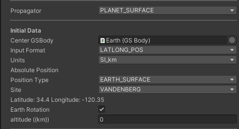
This component will locate the body in physics space at the radius specified by the center body physical info and and the
lattitude and longitude specified by the choice of site or using custom values depending on the POSITION_TYPE selection.
This point will rotate at the rate specified by the center body.
This makes the planet surface point a body in the GECore physics engine allowing scripts to get the current position and use
this to determine e.g. whether a ground station at that point has line of sight to a satellite.
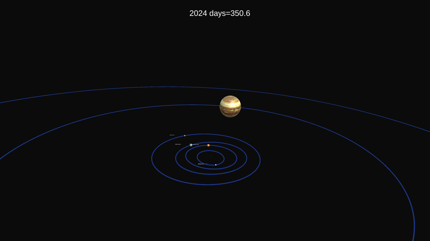
Solar System#
The solar system presents some unique challenges for game visualization and physics modelling in a game engine. Even without the real-time constraints of a game engine, direct numerical modelling of the solar system has several challenges.
In a full N-body code calculations grow as \(N^2\). If we consider the sun, planets and all the moons, there are 294 bodies. A full N-body simulation is expensive and a bit bonkers in a game, since e.g. a moon of Neptune will not have much influence on Mercury.
As discussed in Scaling, there is a big dynamic range between e.g. the orbit of Phobos (9300 km) and the orbit of Neptune (\(4.5 \times 10^9\) km).
The difference in length scale also affects the choice of time scale. We’d need a short time step to evolve Phobos, and if we want to watch Jupiter move in it’s orbit we’d be taking a LOT of time steps.
Scientific code for solar system modelling is complex and nuanced. For the curious, one research grade tool is REBOUND (https://rebound.readthedocs.io/en/latest/). Be aware REBOUND is GNU GPL licensed.
Another issue with creating a solar system model with a reasonable number of bodies is getting the raw data for the masses and orbits of the objects.
Here is where the SolarSystemBuilder is really able to help with the heavy lifting! NASA JPL provides a web site and web API for obtaining information
on bodies in the solar system. This is the JPL Horizons system. The SSB tool makes use of this API to request
information for those planets, moon and small bodies that have been selected in the SSB inspector. This processes is triggered by the “Build System”
button in the SSB inspector. Triggering this event creates all the necessary elements in the scene and makes a request to the JPL web server
for each body. The JPL web server limits the number of open HTTP requests so the SSB does these sequentially. The result is that after pressing
“Build System” it can take a handful of seconds to get all the information. (When the console has stopped logging, the process is complete).
Note that the data requests contain a date/time for which the information is requested.
SolarSystemBuilder#
GE2 provides a SolarSystemBuilder (SSB) editor tool that constructs a solar system scene in a way that mitigates some of the above issues. Instead of creating
a monolithic system for the planets and their moons it creates
independent systems for each planet that has moons. Each of these systems can then have their own visual scale and evolution time frame.
The result is a scene that has a hierarchy along the lines of:
The SSB inspector interface has check boxes for the major planets (sorry, Pluto) and allows the number of moons to be specified. There is also a mechanism for looking up what JPL refers to as “small bodies”. The inspector interface looks like:
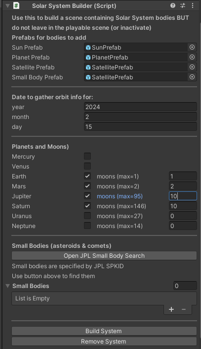
The somewhat cryptic small body codes are explained below.
There are two buttons in the SSB inspector.
Build_Systemcreates a new solar system, all associated controllers, display controllers etc using the prefabs indicated. This will ask JPL Horizons for the orbital elements for the bodies requested. This can take some time to run (watch the console).Remove SystemRemove the created solar system.
The SSB creates a series of controllers and displays for each planetary system. All bodies are sourced from prefabs that have the required GE2 components to model bodies. Specifically each prefab must have a:
GSBodyGSDisplayBodyGSDisplayOrbit(optional)mesh object (e.g. Sphere) as a child (optional)
If the displayable object is referenced by the GSDisplayObject then there are some additional options:
the body can be rotated (if rotation axis and rate information is available in the
GSBody)the size of the object can be scaled up to help make it more visible in the
GSDisplay.
In addition, the SSB will also check for material resources that match a planet or moons name. If found, these will be applied to the mesh object child of the planet or moon.
The radius scaling feature exists because a direct 1:1 scaling of most moons leaves them too small to see in the same view that shows the size of their orbits.
Note that each planetary system with moons has a controller as a top level game object. Within each of these is a GSDisplay, and a typical arrangement of
GSBody, GSDisplayBody and GSDisplayOrbit elements derived from the prefab objects specified in the SolarSystemBuilder inspector.
Each of these controllers would by default run “as is” and they would all evolve their bodies according to their individual scaling and game time per orbit
values. The result would be different controllers evolving at different world time rates and a discordant evolutionary mess. What we need is
an entity to “conduct the choir”, SolarMetaController (SMC). The SMC designates one of the systems to be the primary system and the remainder to be secondary
and gives the secondary controllers a reference to the primary controller. With GSController there is code that will evolve according to the usual game time
rate if the controller is designated as primary. A controller set as secondary will ask the primary controller for the current world time and then evolve to match
that time.
The SolarMetaController also allows the initial conditions of all the controllers in the scene to be adjusted. Specifically:
start time (note that start time must be later than the time specified when creating the solar system)
execution mode (IMMEDIATE or JOB)
To ensure that the evolution is able to manage different time scales all of the elements build by SSB make use of KEPLER mode evolution. This ensures that a system with both Neptune and Phobos is not trying to do lengthy numerical integration to make Phobos spin around Mars at a time scale where we can see Neptune move. Using KEPLER ensures that the new position is computed directly from the time value.
The SolarMetaController also manages issues with displaying objects on very different scales. It assumes that the camera will only be looking at one
of the systems and sets the display GSDisplay of the other systems to inactive (this is a GSDisplay level activity, not the active mode of the game object).
It also adjusts the camera distance based on the scale of the system. SMC uses function keys 0-9 to select the system, F0 selects the Sun as the center and
Fn denotes a center on system “n”. Only those systems with moons will be valid selections.
Note
To compare the scene to the current position of the solar system, take a look a NASA Orrery.
Small Body Specification#
A list of small bodies can be specified in the solar system builder. These are objects orbiting the sun, typically asteroid and comets.
They are specified by a small body reference number. This number is found by using the JPL Horizon small body lookup. A link to this
web page is provided by the Open JPL Small Body Search. This provides a name search and then list matching bodies. For example for
“Halley” we get two responses, one is an asteroid and the other is Halley’s comet. If we pick the later the web page shows something like:
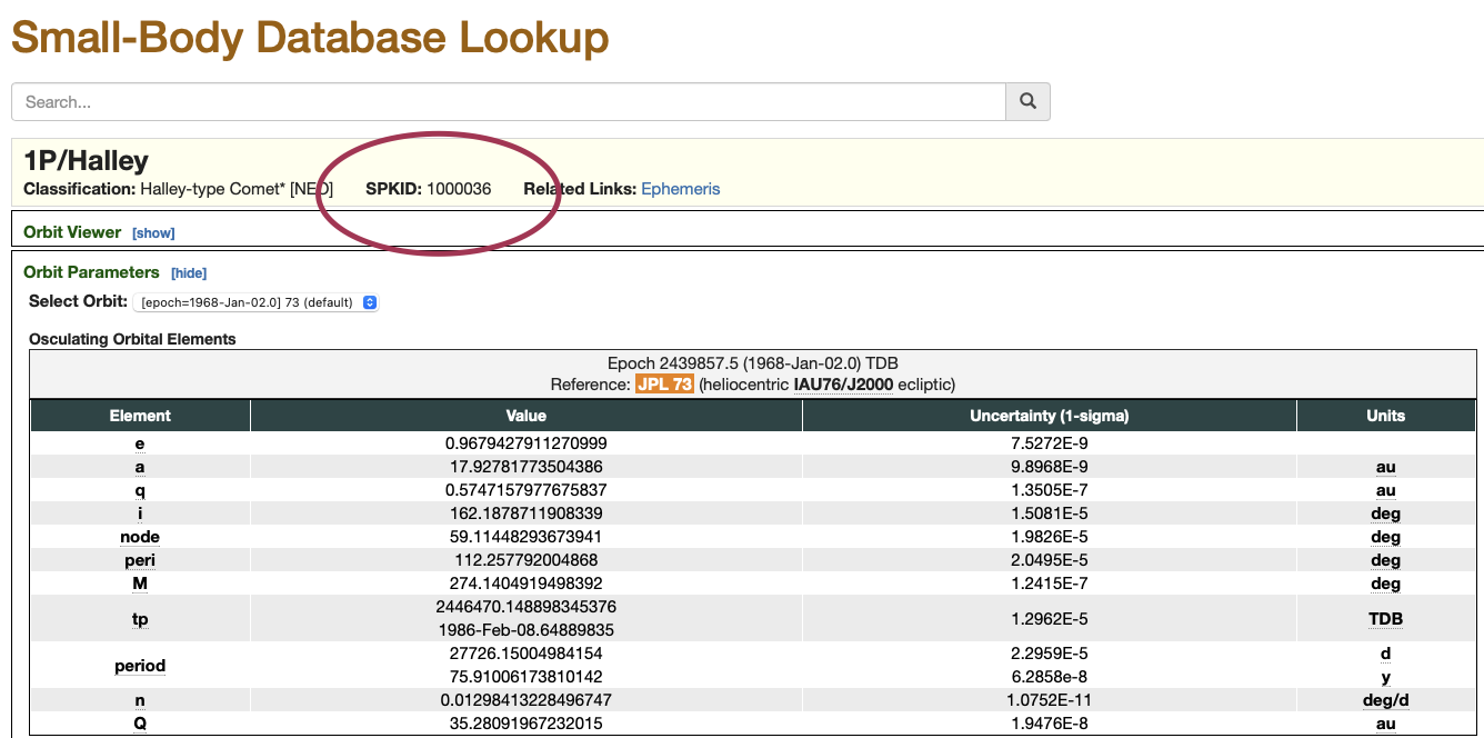
The key info in this response is the SPKID value (in this case 1000036). This is the small body designation we add to the SSB list if we
wish to add Halley’s comet to our solar system build.